Page 15
VII−DIAGRAMS / OPERATING SEQUENCE
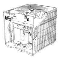
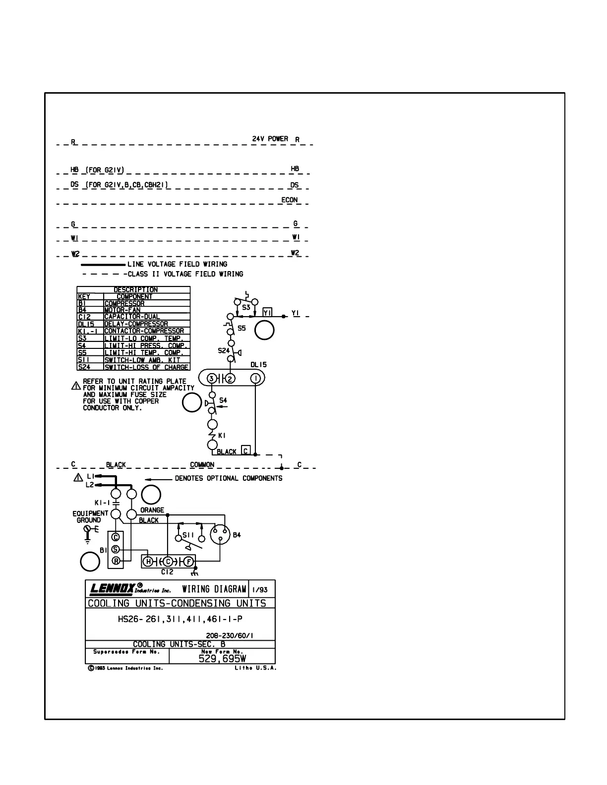
A−Unit Diagram HS26−261/461−1P (Early Models)
UNIT DIAGRAM
1
2
3
4
Operation Sequence
1− WARNING−Early HS26 units use single−
pole contactors. Capacitor terminal
COM," orange condenser fan wire and
red R" compressor wire are all con
nected to L2 at all times. Remove all
power at disconnect before servicing.
2− Cooling demand energizes thermostat ter
minal Y. Voltage from terminal Y passes
through discharge temperature sensor
(compressor thermostat) and low pressure
switch to energize time delay terminal 2.
3− Time delay action is at the beginning of a
thermostat demand. When energized, time
delay TD1−1 delays 8.5 seconds before en
ergizing TD1−1 terminal 3. When TD1−1 ter
minal 3 is energized, the contactor coil is en
ergized.
4− When compressor contactor is energized,
N.O. contactor contacts close to energize
compressor terminal C" (black wire) and
black condenser fan motor wire. Condens
er fan and compressor immediately begin
operating.
 Loading...