Page 37
Gas Valve Operation for Honeywell VR8205 and
VR8305 Series Valve (Figure 27)
ON
OFF
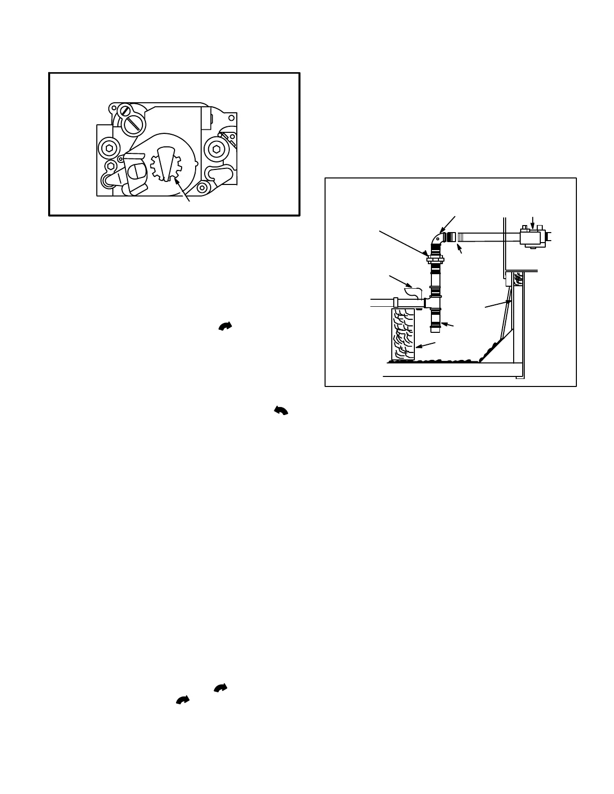
HONEYWELL VR8205 / VR8305 SERIES GAS VALVE
GAS VALVE SHOWN IN OFF POSITION
VR8205 SHOWN
1- Set thermostat to lowest setting.
2- Turn off all electrical power to appliance.
3- This appliance is equipped with an ignition device
which automatically lights burner. Do not try to lightthe
burner by hand.
4- Remove heat section access panel.
5- Turn knob on gas valve clockwise to OFF and re-
lease.
6- Wait five minutes to clear out any gas. If you then smell
gas, STOP! Immediately call your gas supplier from a
neighbor’s phone. Follow the gas supplier’s instruc-
tions. If you do not smell gas go to next step.
7- Turn knob on gas valve 90_ counterclockwise to
on.
8- Replace heat section access panel.
9- Turn on electrical power to unit.
10-Set thermostat to desired setting.
11-The combustion air blower will start. The burners will
light within 40 seconds.
12-If unit does not light first time (gas line not fully purged)
it will attempt up to two more ignitions before locking
out.
13-If lockout occurs, repeat steps 1 through 10.
14-If appliance still will not operate, follow the instructions
“To Turn Off Gas to Unit” and call your service techni-
cian or gas supplier.
2-To Turn Off Gas To Unit
1- Set thermostat to lowest setting.
2- Turnoffall electricalpowerto unit if service is to be per-
formed.
3- Remove heat section access panel.
4- Turn knob on gas valve clockwise to OFF. Depress
knob and turn clockwise to OFF.
D-Safety or Emergency Shutdown
Turn off power to the unit.
V- SYSTEMS SERVICE CHECKS
A-LGA Heating System Service Checks
All LGA units are U.L. and U.L.C. design certified with-
out modification.
Before checking piping, check with gas company or au-
thorities having jurisdictionfor local coderequirements.
Refer to the LGA Installation, Operation and Adjust-
ments instruction for more information.
GAS PIPING
SUPPORT
GROUND
JOINT
UNION
FIGURE 28
GAS PIPING COMPONENTS
FIELD PROVIDED
1/8” (3.2 mm) PRESSURE
TAP
VALVE
MANUAL MAIN
SHUT-OFF VALVE
(REFER TO LOCAL
CODES)
DRIP LEG
ROOF
MOUNTING
FRAME
CAP HERE TO
ISOLATE VALVE
PRESSURE
TESTING
REFER TO INSTALLATION INSTRUCTIONS
1-Gas Piping
Gas supply piping must not allow more than 0.5”W.C.
(124.3 Pa) drop in pressure between the gas meter and
the unit. Supply gas pipe must not be smaller than the unit
gas connection. Refer to installation instructions for de-
tails.
2-Testing Gas Piping
NOTE-In case emergency shutdown is required, turn off
the main manual shut-off valve and disconnect the main
power to the unit. These controls should be properly la-
beled by the installer.
When pressure testing gas lines, the gas valve must be dis-
connected and isolated. Gas valves can be damaged if
subjected to more than 0.5 psig [14”W.C. (3481 Pa)]. See
figure 28.
When checking piping connection for gas leaks, use the
preferred means. Common kitchen detergents can
cause harmful corrosion on various metals used in gas
piping. The use of specialty Gas Leak Detector is
strongly recommended. It is available through Lennox
under part number 31B2001.
Do not use matches, candles, flame or any other source
of ignition to check for gas leaks.
 Loading...


