Page 14
I-UNIT COMPONENTS
LGA / LCA units are configure to order units (CTO). The
LGAandLCAunit componentsare shownin figures1 and2.
L1, L2, and L3 wiring is color coded; L1 is red, L2 is yellow,
and L3 is blue.
A-Control Box Components
LGA/LCA control box components are shown in figure 3.
The control box is located in the upper portion of the com-
pressor compartment.
1-Disconnect Switch S48 (Optional all units)
LGA/LCA units may be equipped with an optional disconnect
switch S48. Other factory or field installed optional circuit
breakers may be used, such as CB10. S48 and CB10 are
toggle switches, which can be used by the service techni-
cian to disconnect power to the unit.
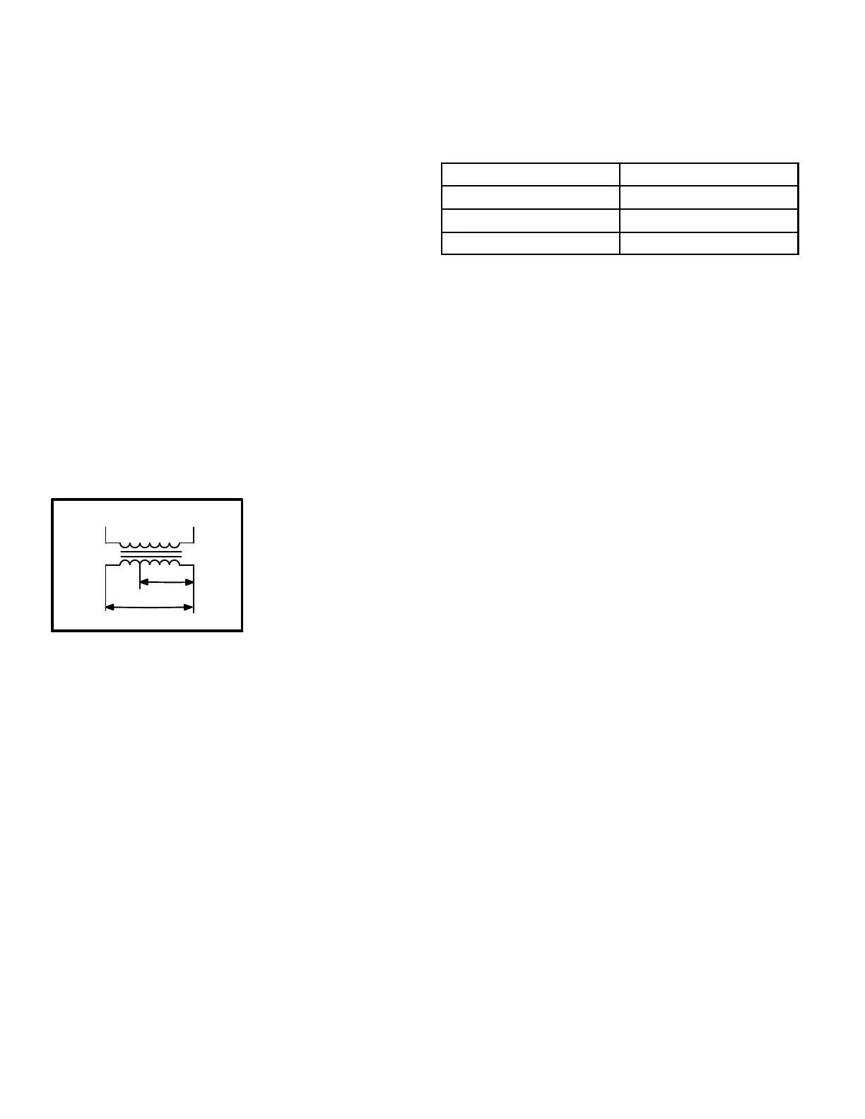
2-Control Transformer T1 (all units)
All LGA/LCA series units use a single line voltage to
24VAC transformer mounted in the control box. Trans-
former supplies power to control circuits in the unit. The
transformer is rated at 70VA and is protected by a 3.5
amp circuit breaker (CB8). The 208/230 (Y) voltage
transformers use two
primary voltage taps
as shown in figure 4,
while 460 (G) and 575
(J) voltage transform-
ers use a single prima-
ry voltage tap.
3-C. A. B. Transformers T3
(LGA 460V & 575V units)
All LGA 460 (G) and 575 (J) voltage units use one auto volt-
age to 230VAC transformer mounted in the compressor
compartment. The transformer has an output rating of 0.5A.
T3 transformer supplies 230 VAC power to combustion air
blower motor (B6).
4-Terminal Strips TB1 and TB34 (all units)
TB1 terminal strip distributes 24V power and common from
thethermostattothe control box components. TB34 termi-
nal strip distributes 24V power from T1 to the control box
components.
5-Unit Fuse Block & Fuses F4 (LCA units)
Line voltage fuses F4 provide short circuit and ground fault
protection to all cooling components in the LCA units with elec-
tric heat. Single phase units use two fuses and three phase
units use three fuses. The fuses are rated in accordance with
the amperage of the cooling components.
6-Outdoor Fan Capacitor C1
(three phase units)
Fancapacitor C1 is used to assist in the start up of condens-
er fan B4. See table 1 for ratings
TABLE 1
Unit Voltage Capacitor Rating
208/230 10MF 370V
460V 10MF 370V
575V 10MF 370V
7-Compressor Contactor K1 (all units)
K1 is a 24Vto line voltage contactor used toenergize the com-
pressor and condenser fan in response tothermostat demand.
Three-phase units use three-pole-double-break contactors.
Single-phase units use two-pole double break contactors.
NOTE-Contactor K1 is energized by the IMC Control sys-
tem. Refer to the operation sequence for the control sys-
tem installed. There may be a 5 minute delay depending
on the system installed.
8-Blower Contactor K3 (all units)
Blower contactor K3 isusedinallunits. In direct drive units, K3
is DPDT relay. In single phase belt drive units, K3 is a DP con-
tactor while three-phase belt drive units use a 3PDB contactor.
K3 has a 24VAC coil used to energize the indoor blower motor
B3, in response to blower demand. K3 is energized by main
control panel (A55).
9-Outdoor Fan Relay K10 (all units)
Outdoor fan relay K10, used in all units, is a DPDT relay with
a 24VAC coil. In all units K10 (energized by A55), energizes
condenser fan B4 in response to thermostat demand. Once
discharge pressure of275¦ psigachieved, operation iscon-
trolled by Low ambient switch (S11).
10-Combustion Air Blower Relay K13
(LGA units )
Combustion air blower relay K13, used in all LGA units, is a
DPDT relay with a 24VAC coil. K13 is energized by the main
control module A55 after a heating demand from the ther-
mostat. K13 remains energized throughout the heating de-
mand. When energized, K13 N.O. contacts close to ener-
gize the combustion air blower and begin a heating
sequence. Pressure switch S18, located in the gas heat
compartment, closes as combustion air static pressure
falls to “prove” combustion air blower operation. When
S18 closes, the ignition controls and gas valves are ener-
gized to begin a heating sequence.
FIGURE 4
BLUE YELLOW
ORANGE
RED
BLACK
230 VOLTS
208 VOLTS
PRIMARY
SECONDARY
208/230V TRANSFORMER
 Loading...


