Page 38
3-Testing Gas Supply Pressure
When testing gas supply pressure, connect test gauge to the
inlet pressure tap (field provided - figure 28). Test supply gas
pressure with unit firing at maximum rate (both stages en-
ergized). Make sure the reading falls within the range of
the following values.Low pressuremay result in erraticop-
eration or “underfire.” High pressure can result in perma-
nent damage to the gas valve or “overfire.” For natural
gas units, operating pressure at the unit gas connection
must be between 5.5”W.C. and 10.5”W.C. (1367 Pa and
2610 Pa) For L.P. gas units, operating pressure at the
unit gas connection must be between 10.8”W.C. and
13.5”W.C. (2685.3 Pa and 3356.7 Pa).
On multiple unit installations, each unit should be checked
separately while operating at maximum rate, beginning with
the one closest to the supply gas main and progressing to
the one furthest from the main. Multiple units should
also be tested with and without the other units operat-
ing. Supply pressure must fall within the range listed in
the previous paragraph.
4-Check and Adjust Manifold Pressure
After line pressure has been checked and adjusted,
check manifold pressure. Move test gauge to the man-
ifold outlet pressure tap located on unit gas valve GV1.
See figure20 or 21 forlocation of pressuretapon the gas
valve.
The manifold pressure is factory set and should not re-
quireadjustment. If manifold pressure is incorrect and no other
source of improper manifold pressure can be found, the valve
must be replaced. Refer to figure 20 or 21 for location of gas
valve (manifold pressure) adjustment screw. See tables below
for normal operating manifold pressure. White Rodgers two
stage valves are adjustable for high fire only. Honeywell two
stage vavles are adjustable for both high fire and low fire.
All gas valves are factory regulated. The gas valve should
completely and immediately cycle off in the event of gas or
power failure. The manual shut-off knob can be used to imme-
diately shut off gas supply.
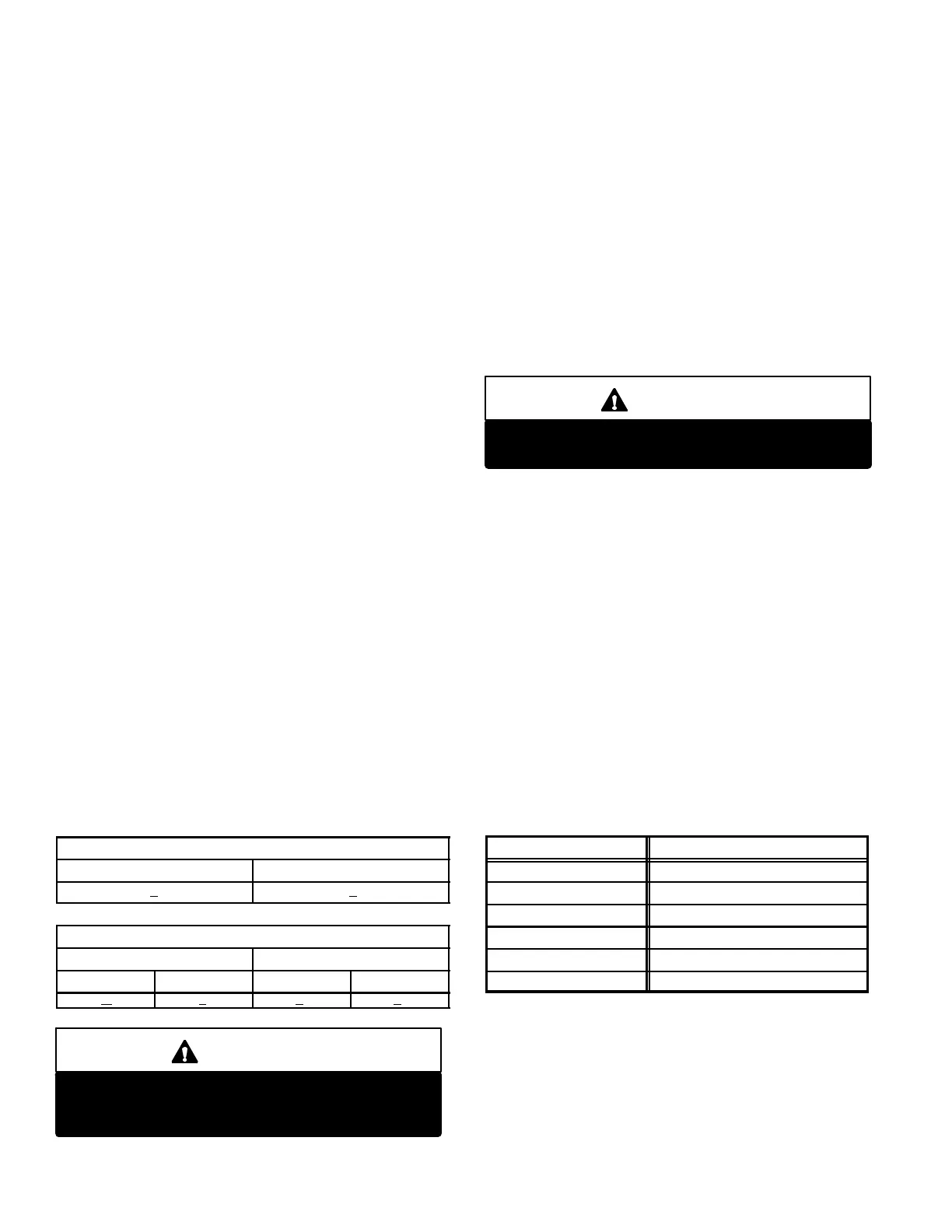
TABLE 21
SINGLE STAGE GAS VALVE FACTORY SETTING
Natural (inlet-5.5” to 10.5”) L.P (inlet-11.0” to 13.0”)
3.5” + 0.3” 10.5” + 0.3”
TABLE 22
TWO STAGE GAS VALVE FACTORY SETTING
Natural (inlet-5.5” to 10.0”) L.P. (11.0” to 13.0”)
High Fire Low Fire High Fire Low Fire
3.7” + 0.3” 1.9” + 0.2” 10.5” + 0.3” 5.32” + 0.2”
CAUTION
For safety, connect a shut-off valve between the
manometer and the gas tap to permit shut off of
gas pressure to the manometer.
Manifold Adjustment Procedure
1- Connect test gauge to the outlet pressure tap on the
gas valve. Start the unit (call for second stage heat)
and allow five minutes for the unit to reach steady
state.
2- While waiting for the unit to stabilize, notice the
flame. The flameshouldbe stable without flashback
and should not lift from the burner heads. Natural
gas should burn basically blue with some clear
streaks. L.P. gas should burn mostly blue with some
clear yellow streaks.
3- After allowing the unit to stabilize for five minutes, re-
cordthe manifold pressure and compare to the values
given for gas supply pressure (above).
CAUTION
Disconnect heating demand as soon as an accurate
reading has been obtained.
5-Proper Gas Flow
To check for proper gas flow to burners, determine Btuh in-
putfrom unit rating plate or thegas heatingcapacitytableon
page 3. Divide this input rating by the Btuh per cubic foot of
available gas. Result is the number of cubic feetper hour re-
quired. Determine the flow of gas through gas meter for two
minutes and multiply by 30 to get hourly flow of gas to the
burners.
NOTE - To obtain accurate reading, shut off all other gas
appliances connected to meter.
6-High Altitude Derate
Natural gas units may be installed at altitudes up to 2000
feet (610m) above sea level without any modification. At al-
titudes above 2000 feet (610 m), units must be derated to
match gas manifold pressures shown inthe following table.
NOTE-This is the only permissible derate for these units.
TABLE 23
Altitude - ft. (m) Gas Manifold Pressure - in. w.g. (kPa)
2001 - 3000 (610 - 915) 3.4 (0.85)
3001 - 4000 (915 - 1220) 3.2 (0.807)
4001 - 5000 (1220 - 1525) 2.9 (0.72)
5001 - 6000 (1525 - 1830) 2.7 (0.67)
6001 - 7000 (1830 - 2135) 2.5 (0.62)
7001 - 8000 (2135 - 2440) 2.3 (0.57)
Derate Procedure:
1- Check manifold pressure at the gas valve pressure tap
with unit operating at high fire (second stage).
2- To reduce maximum input, turn regulator adjusting screw
(figure 20) counterclockwise.
3- Re-check manifold pressure.
 Loading...


