Page 5
LGH/LCH036, 048, 060, 072, 074
Shipping and Packing List
Package 1 of 1 contains:
1- Assembled unit
Check unit for shipping damage. Receiving party should
contact last carrier immediately if shipping damage is found.
General
These instructions are intended as a general guide
and do not supersede local codes in any way.
Authorities having jurisdiction should be consulted
before installation.
The LGH units are available in several heating inputs. The
LCH cooling packaged rooftop unit is the same basic
design as the LGH unit except for the heating section.
Optional electric heat is available for LCH units. LGH and
LCH units have identical refrigerant circuits with
respective 3, 4, 5, and 6 ton cooling capacities.
Standard and high efficiency units are equipped with a
lightweight, all-aluminum condenser coil; optional fin/tube
condenser coils are available. Ultra high efficiency units are
equipped with fin/tube condenser coils.
Units are equipped with the compressors shown in table 1.
TABLE 1
COMPRESSORS
Unit T'Stat Compressor
072H 2-Stage Single-Speed
036S, 048S, 060S,
036H, 048H, 060H, 074H
2- or 3-Stage 2-Step Capacity
036U, 048U, 060U, 074U 2- or 3-Stage
Variable Speed,
2-Step Capacity
036U, 048U, 060U, 074U Zone Sensor Variable Speed
In addition to standard heating and cooling, hot gas
reheat units provide a dehumidifying mode of operation.
Refer to Reheat Operation section.
High efficiency units may be equipped with a Unit
Controller that is factory-configured for “Advanced Air
Flow Control”. This option allows the installer to enter both
the design-specified supply air CFM and outdoor air
CFM. See the Advanced Air Flow Control Start-Up
section. These units are equipped with a variable speed,
direct drive blower and an economizer.
Availability of units and options varies by brand.
Requirements
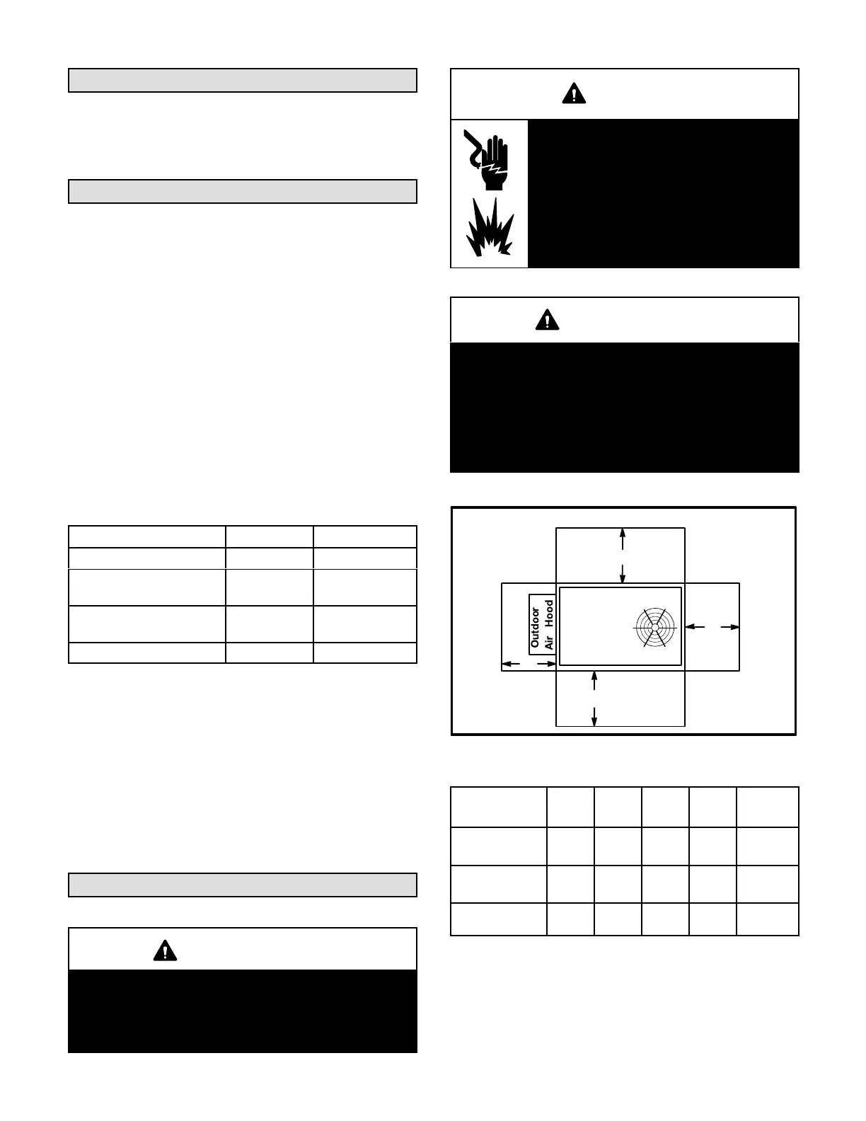
See figure 1 for unit clearances.
IMPORTANT
The Clean Air Act of 1990 bans the intentional vent
ing of refrigerant (CFC's and HCFC's) as of July 1,
1992. Approved methods of recovery, recycling or
reclaiming must be followed. Fines and/or incar
ceration may be levied for non-compliance.
WARNING
Electric shock hazard and danger of
explosion. Can cause injury, death or
product or property damage. Turn off
gas and electrical power to unit before
performing any maintenance or
servicing operations on the unit. Follow
lighting instructions attached to unit
when putting unit back into operation
and after service or maintenance.
NOTICE
Roof Damage!
This system contains both refrigerant and oil.
Some rubber roofing material may absorb oil,
causing the rubber to swell. Bubbles in the rubber
roofing material can cause leaks. Protect the roof
surface to avoid exposure to refrigerant and oil
during service and installation. Failure to follow
this notice could result in damage to roof surface.
UNIT CLEARANCES
C
D
B
A
FIGURE 1
1
Unit
Clearance
A
in.(mm)
B
in.(mm)
C
in.(mm)
D
in.(mm)
Top
Clearance
Service
Clearance
48
(1219)
36
(914)
36
(914)
36
(914)
Unob
structed
Clearance to
Combustibles
36
(914)
1
(25)
1
(25)
1
(25)
Unob
structed
Minimum Opera
tion Clearance
36
(914)
36
(914)
36
(914)
36
(914)
Unob
structed
Note - Entire perimeter of unit base requires support when elevated above
mounting surface.
1
Service Clearance - Required for removal of serviceable parts.
Clearance to Combustibles - Required clearance to combustible material
(gas units).
Minimum Operation Clearance - Required clearance for proper unit operation.
 Loading...


