Page 70
LGH/LCH036, 048, 060, 072, 074
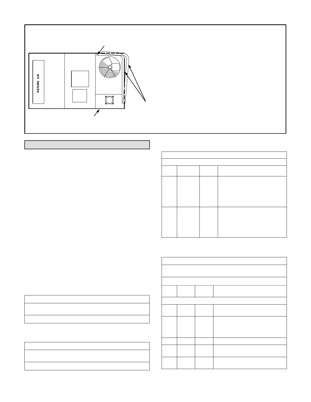
TOP VIEW
CONDENSER
COILS
BLOWER
CONDENSER ACCESS PANEL
FIGURE 37
ENDPLATE IS SECURED
TO MULLION
1- Remove unit top panel and condenser section access
panel.
2- Remove screws securing coil end plate to mullion.
3- Remove wire ties connecting coils slabs and separate
slabs 3-4” (76-102mm).
4- Clean coils with detergent or commercial coil cleaner.
5- Rinse thoroughly with water and reassemble
. Use
field-provided wire ties to connect coil slabs.
CLEAN CONDENSER COIL - UNITS WITH FIN/TUBE COILS
SUPPLY
AIR
Factory Unit Controller Settings
Use the Unit Controller to adjust parameters; menu paths
are shown in each table. Refer to the Unit Controller
manual provided with each unit.
Tables 39 through 42 show factory settings (in degrees, %
of fan CFM, etc.). Record adjusted settings on the label
located inside the compressor access panel.
When field installing optional kits and accessories, the
Unit Controller must be configured to identify the option
before it will function. Refer to figures 38 and 39 to
determine whether the Unit Controller configuration I.D.
must change. To configure the option, use MAIN MENU >
SETUP > INSTALL menu path. Press SAVE until
CONFIGURATION ID 1 or 2 appears depending on the
option installed. Change the appropriate character in the
configuration I.D. For example, when an economizer is
installed using a single enthalpy sensor, change
configuration I.D. 1, the second character, to “S”.
TABLE 39
580730
Units With BACnet Module Settings
Use menu SETUP > NETWORK INTEGRATION. Set “BACNET” and
network address.
BACNET MAC ADDRESS:
TABLE 40
580732
Units With Room Sensor, CPC/LSE Gateway Settings
Use menu SETUP > NETWORK INTEGRATION. Set “L CONNEC
TION” and network address.
LCONN ADDRESS:
TABLE 41
580734
Units With Hot Gas Reheat
Use SETTINGS > RTU OPTIONS > EDIT PARAMETERS
Para
meter
Factory
Setting
Field
Setting
Description
105 6
Hot Gas Reheat Option 6: Reheat is
only possible if blower is energized
during occupied periods. Controlled
by RH sensor (A91) connected to
input A55_P298_5 and set point set
at parameter 106 (default 60%).
414
10 sec
(-036,
-048, -060
All-
Aluminum
Coils only)
HI CL REHEAT TMOUT:
Number of seconds Reheat Valve
remains energized upon thermo
stat call for high stage cooling
(default 0 seconds).
TABLE 42
580735
Units with BACnet Module (Target) Settings
Use menu SETUP > NETWORK INTEGRATION. Set “BACNET”
and network address.
BACNET MAC ADDRESS:
Para
meter
Factory
Setting
Setting Description
Use SETTINGS > RTU OPTIONS > EDIT PARAMETERS
91 120
Sets the compressor minimum run
time to 2 minutes.
106 99
Set reheat SP from connected sensor
to 99% to basically disable. Reheat
will be controlled over by BAS. Only
applies to units with the reheat option.
111 3 Thermostat with three cooling stages.
117 0
DCV max. open damper. 0=controlled
by network.
153 60
Time delay between heating and cool
ing mode.
 Loading...


