Page 15
Gas Flow
To check for proper gas flow to the combustion chamber,
determine the Btu input from the appliance rating plate.
Divide this input rating by the Btu per cubic feet of
available gas. Result is the required number of cubic feet
per hour. Determine the flow of gas through the gas meter
for two minutes and multiply by 30 to get the hourly flow of
gas.
Gas Pressure Adjustment
1 − Check gas line pressure with unit firing at maximum
rate. A minimum of 5" (127mm) w.c. for natural gas
or 11" (279mm) w.c. for LP/propane gas should be
maintained for proper unit operation.
2 − After line pressure has been checked and adjusted,
check regulator pressure. Adjust manifold pressure
to values specified on the unit rating plate. See
figures 8, 9, and 10 for gas pressure adjustment
screw location. A natural gas to LP/propane gas
changeover kit is required to convert unit in the field.
Refer to installation instructions provided with
changeover kit for conversion procedure.
Limit Control Switch
The limit control switch(es) are factory−set and are not
field−adjustable.
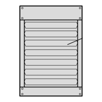
Louver Vane Adjustment
The LF24 series unit heaters are provided with adjustable
louver vanes. Air flow from the unit can be directed down,
straight, out, up, or any combination of these.
WARNING
DO NOT CLOSE the bottom three lou-
vers on LF24. Premature failure to the
heat exchanger can occur.
Combustion Air Pressure Switch
This pressure switch checks for proper combustion air
inducer operation before allowing an ignition trial. The
switch is factory−set and no field adjustment is necessary.
Service
CAUTION
Turn off gas and electrical power to unit before per-
forming any maintenance or service operations on
this unit. Remember to follow lighting instructions
when putting unit back into operation after service
or maintenance.
The unit heater and vent system shall be inspected once a
year by a licensed professional service technician, or
equivalent.
LUBRICATION
1 − Combustion air inducer motor bearings are
pre−lubricated and sealed. No further lubrication is
necessary.
2 − Fan motor bearings should be lubricated according
to manufacturer’s instructions on each motor. If no
instruction is provided, use the following as a guide:
motors with oiling ports are pre−lubricated for an
extended bearing life, re−lubricate with a few drops
of SAE No. 10 non−detergent oil once every two
years.
BURNERS
1 − Periodically examine burner flames for proper
appearance during the heating season.
2 − Before each heating season examine the burners
for any deposits or blockage that may have
occurred.
3 − Clean burners as follows:
a − Turn off both electrical and gas supplies to unit.
b − Disconnect gas supply piping, high tension and
sensor leads. Remove gas manifold. Remove
burner tray.
c − Clean burners as necessary. Make sure that
burner heads line up properly to ensure flame
crossover. Check spark gap on electrode and
adjust if required. The gap should be between
0.110" and 0.140" (2.8 mm to 3.6 mm). The gap
may be checked with appropriately sized twist
drills or feeler gauges.
d − Reinstall burner tray, gas manifold, high
tension and sensor leads. Reconnect gas
supply piping.
e − Restore electrical power and gas supply.
Follow lighting instructions to light unit. Check
burner flame.
 Loading...