Page 16
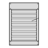
FLUE PASSAGEWAY AND FLUE BOX
The flue passages and flue box should be inspected and
cleaned prior to each heating season. The sequence of
operation should be as follows:
1 − Turn off both electrical and gas supply to unit.
2 − Disconnect combustion air inducer wiring.
3 − Remove screws securing flue box to unit. Remove
flue box. If necessary, remove blower assembly
from flue box. Clean flue box with wire brush.
4 − Remove baffle retention bracket and flue baffles.
Clean flue baffles with wire brush.
5 − Remove burners as described in Burners" section.
6 − Clean tubes with a wire brush.
7 − Reassemble unit. The combustion air and flue box
gaskets should also be replaced during
reassembly.
8 − Restore electrical power and gas supply. Follow
lighting instructions to light unit. Check operation of
unit.
COMBUSTION AIR INDUCER
Under normal operating conditions, the combustion air
inducer should be checked and cleaned prior to the
heating season with the power supply disconnected. Use
a small brush to clean inducer wheel.
ELECTRICAL
1 − Check all wiring for loose connections.
2 − Check for correct voltage at unit (unit operating).
3 − Check amperage draw.
FLUE AND CHIMNEY
Check all vent and vent connector joints for tightness.
Ensure that connections are sealed and that there are no
blockages.
FAILURE TO OPERATE
If unit fails to operate check the following:
1 − Is thermostat calling for heat?
2 − Is main disconnect closed?
3 − Is there a breaker tripped or a fuse blown?
4 − Is gas turned on at meter?
5 − Is manual shutoff valve open?
6 − Is unit ignition system in lock out? If unit locks out
again, call service technician to inspect unit.
7 − Is pressure switch closed? Obstructed flue will
cause unit to shut off at pressure switch. Check flue
passage and outlet.
SAFETY SHUT−OFF VALVE TEST
The safety shut−off valve test procedure is as follows:
1 − Turn off the manual gas valve.
2 − Set the thermostat to call for heat.
3 − System begins normal sequence of operation.
4 − After approximately 30 seconds (pre purge period)
the LED will fast flash indicating the gas valve is
powered.
5 − After 10 seconds, the gas valve closes and steps 4
and 5 will repeat two additional times before locking
out the gas valve, which will be indicated by two
flashes on the LED.
6 − To restart the system, de−energize the thermostat
call for heat and follow the operating instructions
under Unit Start−Up".
REPAIR PARTS
When ordering repair parts include the complete unit
model number listed on the unit rating plate. For example:
LF24−175A−1.
Electrical Connections Tight?
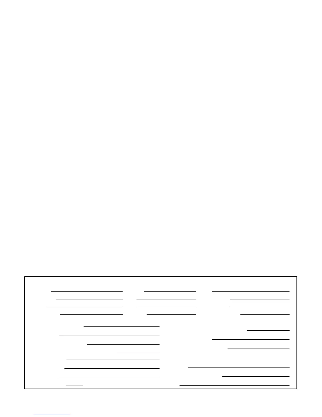
START−UP AND PERFORMANCE CHECKLIST
Job No.:
City:
City:
Serial No.:
Date:
State/Province:
Service Technician:
Air Shutters Properly Adjusted (If Installed)?
Flue Connections Tight?
THERMOSTAT
Calibrated?
Heat Anticipator Properly Set?
Level?
Manifold Pressure
Blower Motor Amps
Blower Motor Lubrication O.K.?
Gas Piping Connections Tight & Leak−Tested?
State/Province:
Fan Timer Operation Checked?
w.c.
Job Name:
Job Location:
Installer:
Unit Model No.:
Supply Voltage
Furnace Btu Input
Line Pressure
 Loading...