Page 14
8 - If B-1 vent or an insulated exible vent pipe cannot
be used as liners, the chimney must be rebuilt
to accommodate one of these methods or some
alternate approved method must be found to vent the
appliance. When inspection reveals that an existing
chimney is not safe for the intended purpose, it
shall be rebuilt to conform to nationally recognized
standards, lined or relined with suitable materials
or replaced with a gas vent or chimney suitable for
venting unit heaters. The chimney passageway must
be checked periodically to ensure that it is clear and
free of obstructions.
REMOVAL OF UNIT FROM COMMON VENT
In the event that an existing unit heater is removed from a
venting system commonly run with separate gas applianc-
es, the venting system is likely to be too large to properly
vent the remaining attached appliances. The following test
should be conducted while each appliance is in operation
and the other appliances are not in operation, yet remain
connected to the common venting system. If the venting
system has been installed improperly, the system must be
corrected.
1 - Seal any unused openings in the common venting
system.
2 - Visually inspect the venting system for proper size and
horizontal pitch. Determine there is no blockage or
restriction, leakage, corrosion, or other deciencies
which could cause an unsafe condition.
3 - In so far as is practical, close all building doors and
windows and all doors between the space in which
the appliances remaining connected to the common
venting system are located and other spaces of the
building. Turn on clothes dryers and any appliances
not connected to the common venting system. Turn
on any exhaust fans, such as range hoods and
bathroom exhausts, so they will operate at maximum
speed. Do not operate a summer exhaust fan. Close
replace dampers.
4 - Follow the lighting instructions. Place the appliance
being inspected in operation. Adjust thermostat so
appliance will operate continuously.
5 - Test for spillage at the draft hood relief opening after
ve minutes of main burner operation. Use the ame
of a match or candle, or smoke from a cigarette,
cigar, or pipe.
6 - After it has been determined that each appliance
remaining connected to the common venting system
properly vents when tested as outlined above, return
doors, windows, exhaust fans, replace dampers
and any other gas-burning appliance to their previous
condition of use.
7 - If improper venting is observed during any of the above
tests, the common venting system must be corrected.
The common venting system should be resized to ap-
proach the minimum size as determined by using the
appropriate tables in Appendix G in the current editions
of the ANSI Z223-1, or the appropriate Category I Nat-
ural Gas and Propane appliances venting sizing tables
in the current standards of the CSA-B149 for installa-
tion compliance codes.
Electrical Connections
NOTE - Local codes may supersede any of the provisions
outlined in this instruction.
The LF25 series unit heaters use a direct spark ignition
system. There is no pilot necessary as the spark lights
the main burner as the gas valve is turned on. The di-
rect spark ignition control board emits radio noise as the
sparking process is under way. The level of energy may
be sucient to disturb a logic circuit in a microprocessor
controlled thermostat. It is recommended that an isola-
tion relay be used when connecting the unit heaters to a
microprocessor controlled thermostat. Install the thermo-
stat according to instructions provided. Install a separate
fused disconnect switch, with the fuse sized according to
blower motor size. Connect wiring through knockout on
the junction box located on the side of the unit heater. Re-
fer to dimensions in the front of this instruction for location.
Refer to heater wiring diagram for connection information.
Use 18 gauge wire or larger for thermostat connections.
NOTE - Electrically ground unit in accordance with local
codes or, in the absence of local codes, in accordance
with the current editions of the ANSI/NFPA No. 70, Na-
tional Electrical Code or CSA C22.1, Canadian Electrical
Code, Part 1.
NOTE - Uninsulated ground wires must be wrapped in
electrical tape to avoid damage to the electrical system.
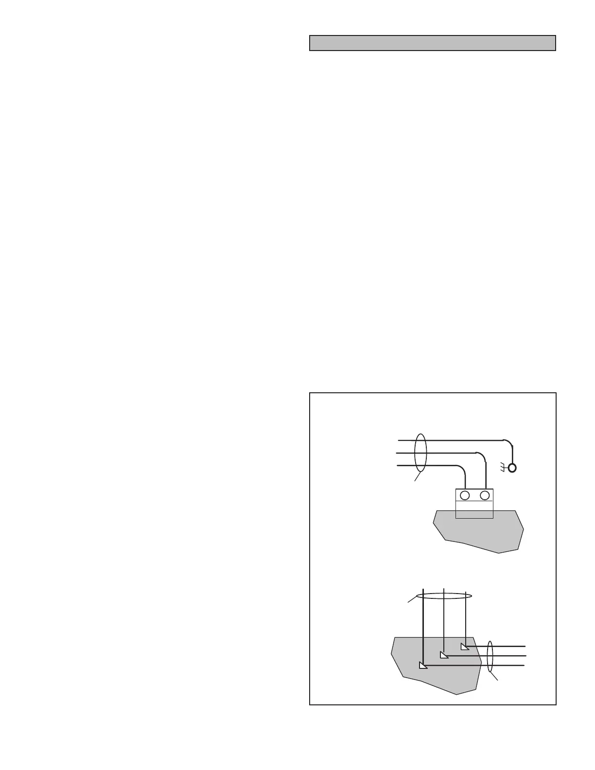
Make line voltage connections as shown in gure 7. Con-
nect eld wiring as shown on wiring diagram on unit. Also
refer to typical diagram in this manual. An additional ther-
mostat wire must be run to terminal “G” on heater when
continuous blower is desired.
HIGH VOLTAGE WIRING
A3 IGNITION
CONTROL
L1
N
GND
FIELD PROVIDED POWER WIRING.
CONNECT TO P366 ON A3 IGNI
TION CONTROL AND GREEN
GROUND SCREW NEAR A3.
GRN-YEL
WHT
BLK
125 / 400
030 / 105
POWER
ENTRY BOX
L1N
L1NGND
FIELD PROVIDED POWER
WIRING. MAKE FIELD
POWER CONNECTIONS
IN POWER ENTRY BOX
L1N
J366
P366
GRN-YEL
WHT
BLK
FACTORY
INSTALLED
FIGURE 7
 Loading...