Page 21
Limit Control Switch
The limit control switch(es) is factory-set and is not
eld-adjustable.
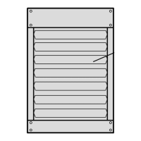
Louver Vane Adjustment
Rotate louver vanes to direct airow upward, downward,
straight, or any combination of these directions. When
30/105 units are is installed in an inverted position, lou-
vers must be removed and rotated 180 degrees as shown
in the installation section.
Combustion Air Pressure Switch
This pressure switch checks for proper combustion air
inducer operation before allowing an ignition trial. The
switch is factory-set. No eld adjustment is necessary. For
high altitude applications, see the Engineering Handbook.
Flame Rollout Switch
This normally closed switch opens on a temperature rise.
See the parts arrangement for location. These switches
are not adjustable.
Service
CAUTION
Turn o gas and electrical power to unit before performing
any maintenance or service operations on this unit.
Remember to follow lighting instructions when putting
unit back into operation after service or maintenance.
The unit heater and vent system shall be inspected once
a year by a licensed professional service technician, or
equivalent.
BURNERS
1 - Periodically examine burner ames for proper
appearance during the heating season.
2 - Before each heating season examine the burners for
any deposits or blockage that may have occurred.
3 - Clean burners as follows:
a. Turn o both electrical and gas supplies to unit.
b. Disconnect gas supply piping, high tension and
sensor leads. Remove gas manifold. Remove
burner box top. Remove burner cluster assembly.
c. Clean burners as necessary. Make sure that
burner heads line up properly to ensure ame
crossover. Check spark gap on electrode and
adjust if required. The gap should be between
0.110” and 0.140” (3mm to 4mm). The gap may
be checked with appropriately sized twist drills or
feeler gauges.
d. Reinstall burner cluster assembly, burner box
top, gas manifold, high tension and sensor leads.
Reconnect gas supply piping.
e. Restore electrical power and gas supply. Follow
lighting instructions to light unit. Check burner
ame.
FLUE PASSAGEWAY AND FLUE BOX
The ue passages and ue box should be inspected and
cleaned prior to each heating season. The sequence of
operation should be as follows:
1 - Turn o both electrical and gas supply to unit.
2 - Disconnect combustion air inducer wiring.
3 - Remove combustion air inducer assembly. Remove
ue box. If necessary, remove inducer assembly
from ue box. Clean ue box with wire brush.
4 - Remove burners as described in “Burners” section.
5 - Clean tubes with a wire brush.
6 - Reassemble unit. The combustion air and ue box
gaskets should also be replaced during reassembly.
7 - Restore electrical power and gas supply. Follow
lighting instructions to light unit. Check operation of
unit.
COMBUSTION AIR INDUCER
Under normal operating conditions, the combustion air in-
ducer should be checked and cleaned prior to the heating
season with the power supply disconnected. Use a small
brush to clean inducer wheel.
ELECTRICAL
1 - Check all wiring for loose connections.
2 - Check for correct voltage at unit (unit operating).
3 - Check amperage draw.
FLUE AND CHIMNEY
Check all vent and vent connector joints for tightness. En-
sure that connections are sealed and that there are no
blockages.
FAILURE TO OPERATE
If unit fails to operate check the following:
1 - Is thermostat calling for heat?
2 - Is main disconnect closed?
3 - Is there a breaker tripped or a fuse blown?
4 - Is gas turned on at meter?
5 - Is manual shuto valve open?
6 - Is unit ignition system in lock out? If unit locks out
again, call service technician to inspect unit.
7 - Is pressure switch closed? Obstructed ue will
cause unit to shut o at pressure switch. Check ue
passage and outlet.
SAFETY SHUT-OFF VALVE TEST
The safety shut-o valve test procedure is as follows:
1 - Turn o the manual gas valve.
2 - Set the thermostat to call for heat.
3 - System begins normal sequence of operation.
 Loading...