Page 8
TABLE 1
UNIT CLEARANCES TO COMBUSTIBLE MATERIALS
Unit
Top Side** Bottom Back Flue
in mm in mm in mm in mm in mm
030/105 1 25 1 25 1 25 18 457 6* 152
125/400 6 152 18 457 1 25 18 457 6 152
*6” is for single wall. Double wall B-vent clearance will be
in accordance with the manufacturer’s listing.
**Access panel or control box side of unit should have 24”
(610mm) clearance.
Additional Requirements
The Commonwealth of Massachusetts stipulates the fol-
lowing additional requirements:
1 - Gas furnaces shall be installed by a licensed
plumber or gas tter only.
2 - The gas cock must be “T handle” type.
Unit Heater Installation
The appliance shall not be installed downstream from
evaporator coils or cooling units.
Install the unit in the desired location as governed by
clearances, vent connection, air direction, gas supply,
electrical supply and service accessibility.
Unit is shipped ready for installation.
CAUTION
Do not install unit heaters in close proximity to re
sprinklers. Unit heater normal operating temperatures
could result in re sprinkler activation.
LF25-125/400 UNITS
Four mounting nuts are furnished. Refer to dimension
illustration. Mounting nuts will accommodate 3/8” x 16
threaded rods.
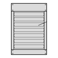
1 - Push each louver to the left to depress spring and
release locking tab on the other end (locking tab
keeps the louver in place for shipping).
2 - Rotate louvers to direct airow as desired.
3- Cut threaded rods to desired length and slide a 3/8”
nut onto the rod.
4 - Slide a at washer onto the threaded rod AFTER the
nut (7/16” inside diameter X 1” outside diameter X
1/16” thick washer).
5 - Screw the rods (two or four) into the mounting nuts
on the unit.
6 - Tighten nuts to secure unit to rods.
TABLE 2
MAXIMUM MOUNTING HEIGHTS - 125/400
Unit Feet (Meters)
LF25-125/150 16 (4.9)
LF25-175/200 20 (6.1)
LF25-250/400 30 (9.1)
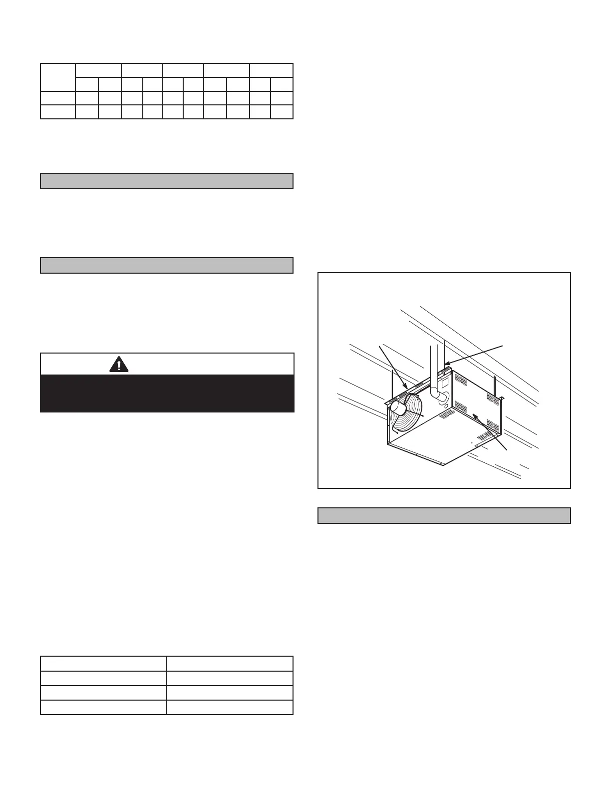
LF25-30/105
Unit may be installed as shown in gure 1 or rotated
180°.
1 - Push each louver to the right to depress spring and
release locking tab on the other end (locking tab
keeps the louver in place for shipping).
2 - If installing unit in a rotated position - release locking
tabs in the same manner as previous step. Rotate
each louver 180° and reinstall. Remove and retain
screws securing access panel. Rotate access panel
180° and resecure using retained screws.
3 - Rotate louvers to direct airow as desired.
4 - Choose location for mounting brackets.
5 - Align mounting brackets with pilot holes on the top or
bottom (when rotating) edge of the unit. Secure with
screws provided in bag assembly.
6 - To support unit, secure mounting bracket to ceiling
joist or truss. Unit may also be supported using
support rods as shown in gure 1.
INSTALL UNIT HEATER
SUPPORT
RODS
MOUNTING
BRACKETS
(2)
ACCESS PANEL
(030 / 105 SHOWN)
FIGURE 1
Combustion and Ventilation Air
Adequate facilities for supplying air for combustion and
ventilation must be provided in accordance with the cur-
rent edition of ANSI Z223.1, section 5.3 and CSA-B149
installation compliance codes, or applicable provisions of
local building codes.
All gas-red appliances require air to be used for com-
bustion. In many buildings today, there is a negative in-
door air pressure caused by exhaust fans, etc. If sucient
quantities of combustion air are not available, the heater
 Loading...