Page 9
or another appliance will operate in an inecient manner,
resulting in incomplete combustion which can result in the
production of excessive carbon monoxide.
WARNING
Insucient combustion air can cause headaches,
nausea, dizziness or asphyxiation. It will also cause
excess water in the heat exchanger resulting in rusting
and premature heat exchanger failure. Excessive
exposure to contaminated combustion air will result
in safety and performance related problems. Avoid
exposure to the following substances in the combustion
air supply:
Permanent wave solutions
Chlorinated waxes and cleaners
Chlorine base swimming pool chemicals
Water softening chemicals
De-icing salts or chemicals
Carbon tetrachloride
Halogen type refrigerants
Cleaning solvents (such as perchloroethylene)
Printing inks, paint removers, varnishes, etc.
Hydrochloric acid
Cements and glues
Antistatic fabric softeners for clothes dryers
Masonry acid washing materials
If indoor air is to be used for combustion, it must be
free of the following substances or the life of the heat
exchanger will be adversely aected: chlorine, car-
bon tetrachloride, cleaning solvent, halogen refriger-
ants, acids, cements and glues, printing inks, uorides,
paint removers, varnishes, or any other corrosives.
Rotation of Combustion Air Inducer (LF25-125 & 150 Only)
The combustion air inducer on LF25-125 & 150 may be
rotated 90° either to the left or right of the original vertical
position in order to better suit the application.
NOTE - It is not permissible to rotate the combustion air
inducer on LF25-030/105 and -175/400.
Rotate the combustion air inducer assembly as follows:
1 - Remove the heater from the carton. Decide the best
unit heater orientation. The vent can be installed in
one of three discharge positions: up, left, or right.
2 - If the inducer is to be rotated, follow the instructions
in this section; otherwise, refer to instructions under
“Venting” section.
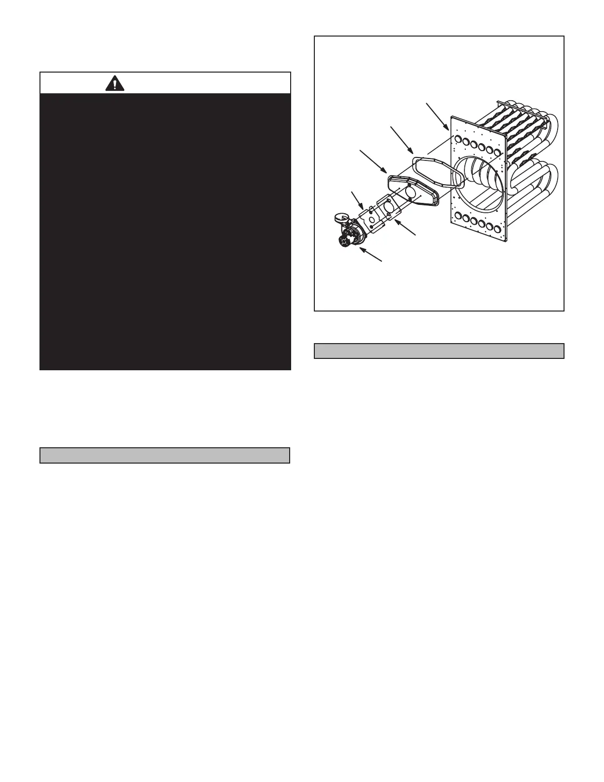
3 - Before making an electrical or gas connections, use
a socket to remove the four screws which secure the
combustion air inducer to the ue box. See gure 2.
4 - Rotate the inducer 90° to the desired position.
Reinsert and tighten the inducer securing screws.
5 - The unit heater is now ready for installation as
described in the Venting section.
FLUE BOX AND COMBUSTION AIR
INDUCER ASSEMBLY
125/150
FLUE BOX
FLUE BOX
GASKET
ORIFICE
PLATE
VEST PANEL
ORIFICE
PLATE GASKET
COMBUSTION
AIR INDUCER
FIGURE 2
Venting
NOTE - The vent is a passageway, vertical or nearly so,
used to convey ue gases from an appliance, or its vent
connector, to the outside atmosphere. The vent connector
is the pipe or duct that connects a fuel-gas-burning appli-
ance to a vent or chimney.
NOTE - Local codes may supersede any of these provisions.
GENERAL RECOMMENDATIONS AND
REQUIREMENTS
Unit heaters must be vented in compliance with the lat-
est edition of the National Fuel Gas Code (NFPA 54 /
ANSI Z223.1) in the USA and with CSA-B149.1 codes in
Canada, as well as applicable provisions of local building
codes, and the following instructions.
030-150 Units - The transition is a part of the combus-
tion air blower.
175-400 Units - A stamped/extruded metal transition
is supplied with this certied unit. It must not be mod-
ied or altered and must be installed on the outlet
of the combustion air inducer assembly prior to the
installation of the vent connector. Failure to comply
with this requirement will void the certication of the
unit by the approval agencies.
A single-wall vent connector may be used between the
furnace and the vertical vent pipe in all applications; how-
ever, single-wall vent material cannot be used for
vertical vent piping in residential applications. UL-ap-
proved Category III venting materials must be used
in all residential applications which vent horizontally.
 Loading...