Page 13
LGH/LCH036, 048, 060, 072, 074
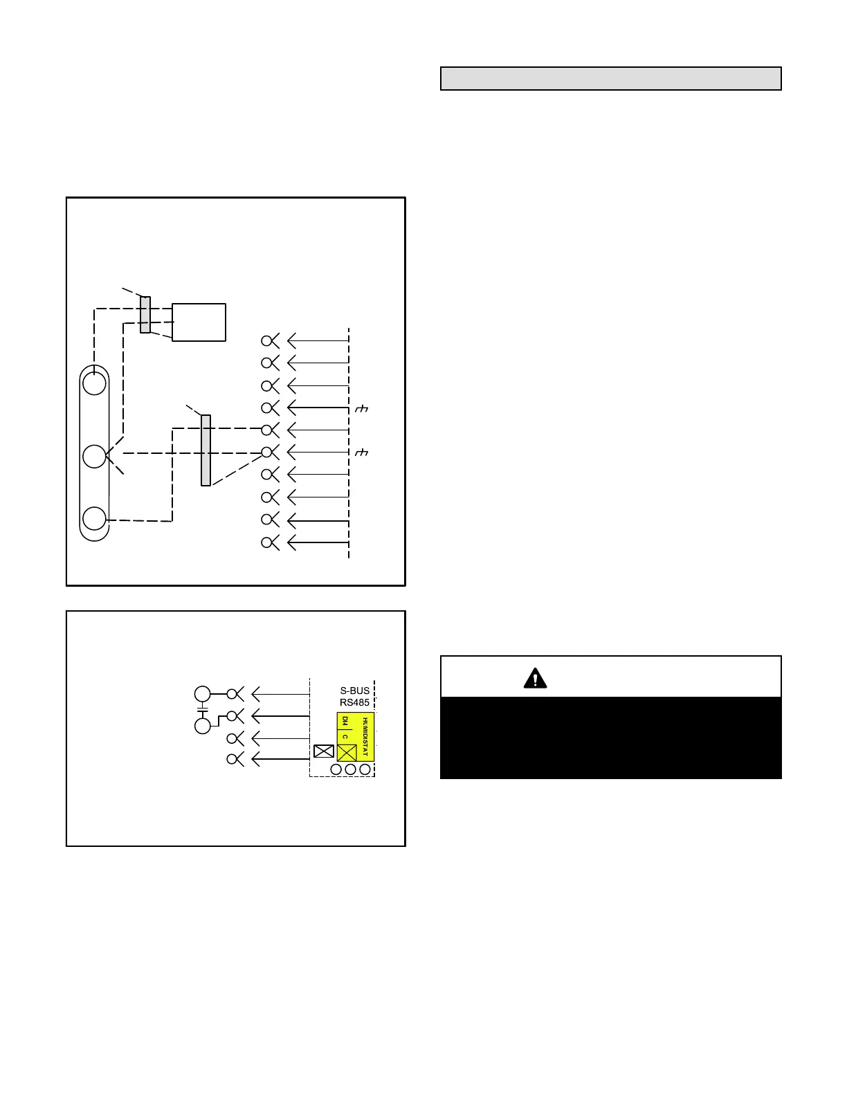
Wire runs over 150 feet (mm):
Use a local, isolated 24VAC transformer such as
Lennox cat #18M13 (20VA minimum) to supply power
to RH sensor as shown in figure 17. Use two shielded
cables containing 20AWG minimum, twisted pair
conductors with overall shield. Belden type 8762 or
88760 (plenum) or equivalent.
FIGURE 17
FIELD WIRING REHEAT UNITS
(Using A Humidity Sensor With
More than 150 Ft. Wire Runs)
ISOLATED 24V
TRANSFORMER
9
8
P298
J298A
1
2
B
3
4
C
5
6
7
D
10
A91
VIN
VO
GND
R
C
AI-1
HUM
TMP
DO-1
C
DI-1
DO-2
NOT
CONNECTED
NOT
CONNECTED
DRAIN
A55 UNIT
CONTROLLER
FIGURE 18
FIELD WIRING REHEAT UNITS
(Using A Dehumidification Switch)
7
10
8
9
R
DI−4
C
Use 24 VAC (R) from any terminal
available on J299−2, −5, or −7.
J299
DEHUMIDIFICATION
SWITCH
Blower Operation and Adjustments
Units are equipped with one of three factory-installed
blower options. The ninth character in the model number
identifies the blower as follows:
E= High efficiency three-, four- and five-ton units are
equipped with a variable speed, direct drive blower.
When these units are also equipped with an
economizer and configured for Advanced Air Flow
Control, the installer is able to enter the
design-specified supply and outdoor air CFM into
the Unit Controller. This eliminates the need to
manually take measurements and adjust settings.
See Advanced Air Flow Control Start-Up section.
Ultra high efficiency units are also equipped with a
variable speed, direct drive blower. The installer is
able to enter the design-specified supply air CFM
into the Unit Controller for optimal efficiency. The
Unit Controller calibrates the supply air volume
which eliminates the need to manually take duct
static measurements. Refer to D-Adjusting Unit
CFM - Ultra High Efficiency Direct Drive Blowers.
T= Units are equipped with a two-stage belt drive blower.
B= Units are equipped with a single-stage belt drive
blower.
Note - Six-ton, non-ultra high efficiency units are
available with belt drive blowers only.
IMPORTANT
Three phase scroll compressors must be phased
sequentially for correct compressor and blower
rotation. Follow “COOLING START-UP” section of
installation instructions to ensure proper compres
sor and blower operation.
 Loading...