Page 57
LGH/LCH036, 048, 060, 072, 074
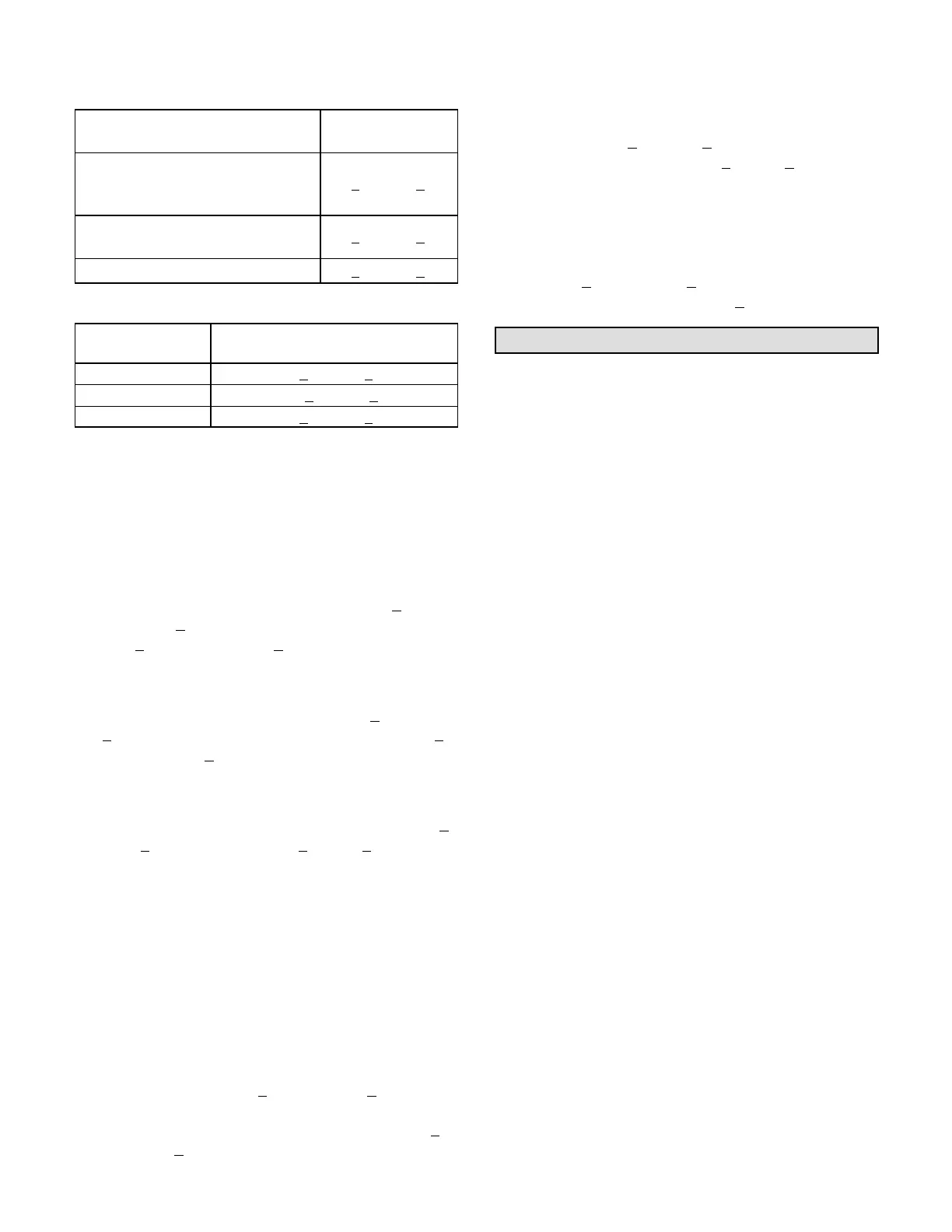
TABLE 33
APPROACH TEMPERATURE
LGH/LCH Unit
Liquid Temp. Minus
Ambient Temp.
036S & H Std.; 036S & H Reheat;
048S & H Std.;
072H Std.; 074H Std.
6°F + 1 (3.3°C + 0.5)
048S & H Reheat;
072H Reheat; 074H Reheat
7°F + 1 (3.9°C + 0.5)
060S & H Std.; 060S/H Reheat 8°F + 1 (4.4°C + 0.5)
TABLE 34
SUBCOOLING TEMPERATURE
LGH/LCH Unit
Liquid Saturated Temp. Minus
Liquid Temperature
036U; 060U 15°F + 1 (8.3°C + 0.5)
048U 15.5°F + 1 (8.6°C + 0.5)
074U 16°F + 1 (8.8°C + 0.5)
F-Compressor Controls
See unit wiring diagram to determine which controls are
used on each unit. Optional controls are identified on
wiring diagrams by arrows at junction points.
1- High Pressure Switch (S4)
The compressor circuit is protected by a high
pressure switch which opens at 640 psig +
10 psig
(4413 kPa +
70 kPa) and automatically resets at 475
psig +
20 psig (3275kPa + 138 kPa).
2- Low Pressure Switch (S87)
The compressor circuit is protected by a loss of
charge switch. Switch opens at 40 psig +
5 psig (276
+ 34 kPa) and automatically resets at 90 psig + 5
psig (621 kPa +
34 kPa).
3- Freezestat (S49)
The compressor is protected by a freezestat located
on the indoor coil. The freezestat opens at 29F+3
(-2C+
2) and closes at 58F+4 (14C+2).
4- Compressor Crankcase Heater (HR1)
Crankcase heater must be energized at all times to
prevent compressor damage due to refrigerant
migration. Energize crankcase heater 24 hours before
unit start-up by setting thermostat so that there is no
cooling demand (to prevent compressor from cycling)
and apply power to unit.
5- Low Ambient Pressure Switch (S11)
Switch maintains adequate discharge pressure by
de-energizing condenser fan when liquid pressure
falls below 240 psig +
10 (1655 kPa+69). S11 is
installed in the liquid line. Switch closes to energize
condenser fan when pressure rises to 450 psig +
10
(3103kPa + 69).
6- Discharge Line Thermostat (S40)
3 through 5 Ton Non-Ultra Units Only
Switch opens when discharge line temperature
reaches 94F+
5 (34C+3) and closes when
temperature falls below 74F+
5 (23C+3). Prevents
crankcase heater operation in warm weather.
7- High Ambient Pressure Switch (S16)
Switch improves high ambient operation by
activating the TXV assist circuit. Switch closes at
550psig +
10 (3792kPa + 70kPa) and automatically
resets at 400 PSIG (2758kPa +
70kPa).
Cooling Operation
036S/H, 048S/H, 060S/H, 074H UNITS
This is a summary of cooling operation. Refer to the
sequence of operation provided in the Engineering
Handbook or Service Manual for more detail.
Note - During a dehumidification demand the blower
operates at low speed. Free cooling is locked-out during
reheat operation. Refer to hot gas reheat start-up and
operation section for details.
A-Two-Stage Thermostat
1-Economizer With Outdoor Air Suitable
Y1 Demand -
Compressor Off
Blower Low
Dampers modulate
Y2 Demand -
Compressor Off
Blower High
Dampers Modulate
Note - If dampers are at maximum open for three
minutes, compressor is energized at high speed and
blower stays on cooling high.
2-No Economizer or Outdoor Air Not Suitable
Y1 Demand -
Compressor Low
Blower Low
Dampers Minimum Position
Y2 Demand -
Compressor High
Blower High
Dampers Minimum Position
 Loading...