Page 22
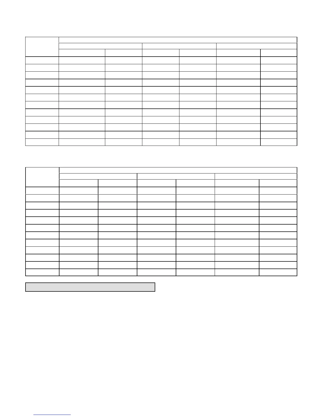
TABLE 4
MANUFACTURER'S NUMBERS - NO TENSIONER
DRIVE NO.
DRIVE COMPONENTS
ADJUSTABLE SHEAVE FIXED SHEAVE BELT
BROWNING NO. OEM PART NO. BROWNING NO. OEM PART NO. BROWNING NO. OEM PART NO.
1 1VP34x7/8 31K6901 AK61x1 100244-20 AX54 100245-25
2 1VP40x7/8 79J0301 AK59x1 31K6801 AX55 100245-26
3 1VP34x7/8 31K6901 AK46x1 100244-17 AX52 100245-33
4 1VP44x7/8 53J9601 AK74x1 100244-21 AX58 100245-34
5 1VP50x7/8 P-8-2187 AK69x1 37L4701 AX58 100245-34
6 1VP50x7/8 P-8-2187 AK64x1 12L2501 AX57 100245-28
7 1VP44x1-1/8 36C0701 AK74x1 100244-21 AX58 100245-34
8 1VP50x1-1/8 P-8-1977 AK69x1 37L4701 AX58 100245-34
9 1VP50x1-1/8 P-8-1977 AK64x1 12L2501 AX57 100245-28
10 1VP50x1-1/8 P-8-1977 BK77x1 49K4001 BX59 59A5001
11 1VP50x1-1/8 P-8-1977 BK67x1 100244-24 BX57 78L5301
12 1VP50x1-1/8 P-8-1977 BK62x1 100244-23 BX56 100245-11
TABLE 5
MANUFACTURER'S NUMBERS - WITH TENSIONER
DRIVE NO.
DRIVE COMPONENTS
ADJUSTABLE SHEAVE FIXED SHEAVE BELT
BROWNING NO. OEM PART NO. BROWNING NO OEM PART NO. BROWNING NO. OEM PART NO.
1T 1VP44X7/8 P81488 BK95X1 79J2701 BX68 88K3401
2T 1VP50X7/8 P82187 BK90X1 P89659 BX68 88K3401
3T 1VP56X7/8 P81494 BK85X1 49K4101 BX69 10024551
4T 1VP44X7/8 P81488 BK77X1 49K4001 BK66 88K3301
5T 1VP56X7/8 P81494 BK85X1 49K4101 BX69 10024551
6T 1VP50X7/8 P82187 BK67X1 10024424 BX65 10024508
7T 1VP44X11/8 10023907 BK77X1 49K4001 BX68 88K3401
8T 1VP56X11/8 P81492 BK85X1 49K4101 BX70 31K9601
9T 1VP50X11/8 P81977 BK67X1 10024424 BX66 88K3301
10T 1VP50X11/8 P81977 BK77X1 49K4001 BX68 88K3401
11T 1VP50X11/8 P81977 BK67X1 10024424 BX66 88K3301
12T 1VP50X11/8 P81977 BK62X1 10024423 BX66 88K3301
Cooling Start-Up
IMPORTANT-The crankcase heater must be energized
for 24 hours before attempting to start compressor. Set
thermostat so there is no demand to prevent
compressors from cycling. Apply power to unit.
A-Preliminary Checks
1- Make sure that unit is installed in accordance with the
installation instructions and applicable codes.
2- Inspect all electrical wiring, both field‐ and
factory‐installed, for loose connections. Tighten as
required.
3- Check to ensure that refrigerant lines do not rub against
the cabinet or against other refrigerant lines.
4- Check voltage at disconnect switch. Voltage must be
within range listed on nameplate. If not, consult
power company and have voltage condition
corrected before starting unit.
5- Make sure filters are in place before start‐up.
B-Start-Up
Supply Air Inverter Units - Refer to the Belt Drive
Supply Air Inverter Start-Up or Direct Drive Variable
Blower section.
1- Initiate first and second stage cooling demands
according to instructions provided with thermostat.
2- First-stage thermostat demand will energize
compressor 1. Second-stage thermostat demand will
energize compressor 2. On units with an economizer,
when outdoor air is acceptable, a first-stage demand

 Loading...


