Page 47
II-PLACEMENT AND INSTALLATION
Make sure the unit is installed in accordance with the in
stallation instructions and all applicable codes. See ac
cessories section for conditions requiring use of the op
tional roof mounting frame (C1CURB10).
III-CHARGING
WARNING
Refrigerant can be harmful if it is inhaled. Refrigerant
must be used and recovered responsibly.
Failure to follow this warning may result in person
al injury or death.
IMPORTANT
Units equipped with a Hot Gas Reheat system MUST be
charged in standard cooling mode.
A-Refrigerant Charge and Check - All-Aluminum Coil
092H, 102H, 120H, 150S Units
WARNING-Do not exceed nameplate charge under any
condition.
This unit is factory charged and should require no further
adjustment. If the system requires additional refrigerant, re
claim the charge, evacuate the system, and add required
nameplate charge.
NOTE - System charging is not recommended below 60_F
(15_C). In temperatures below 60_F (15_C), the charge
must be weighed into the system.
If weighing facilities are not available, or to check the
charge, use the following procedure:
IMPORTANT - Charge unit in standard cooling mode.
1- Make sure outdoor coil is clean. Attach gauge manifolds
and operate unit at full CFM in cooling mode with econo
mizer disabled until system stabilizes (approximately five
minutes). Make sure all outdoor air dampers are closed.
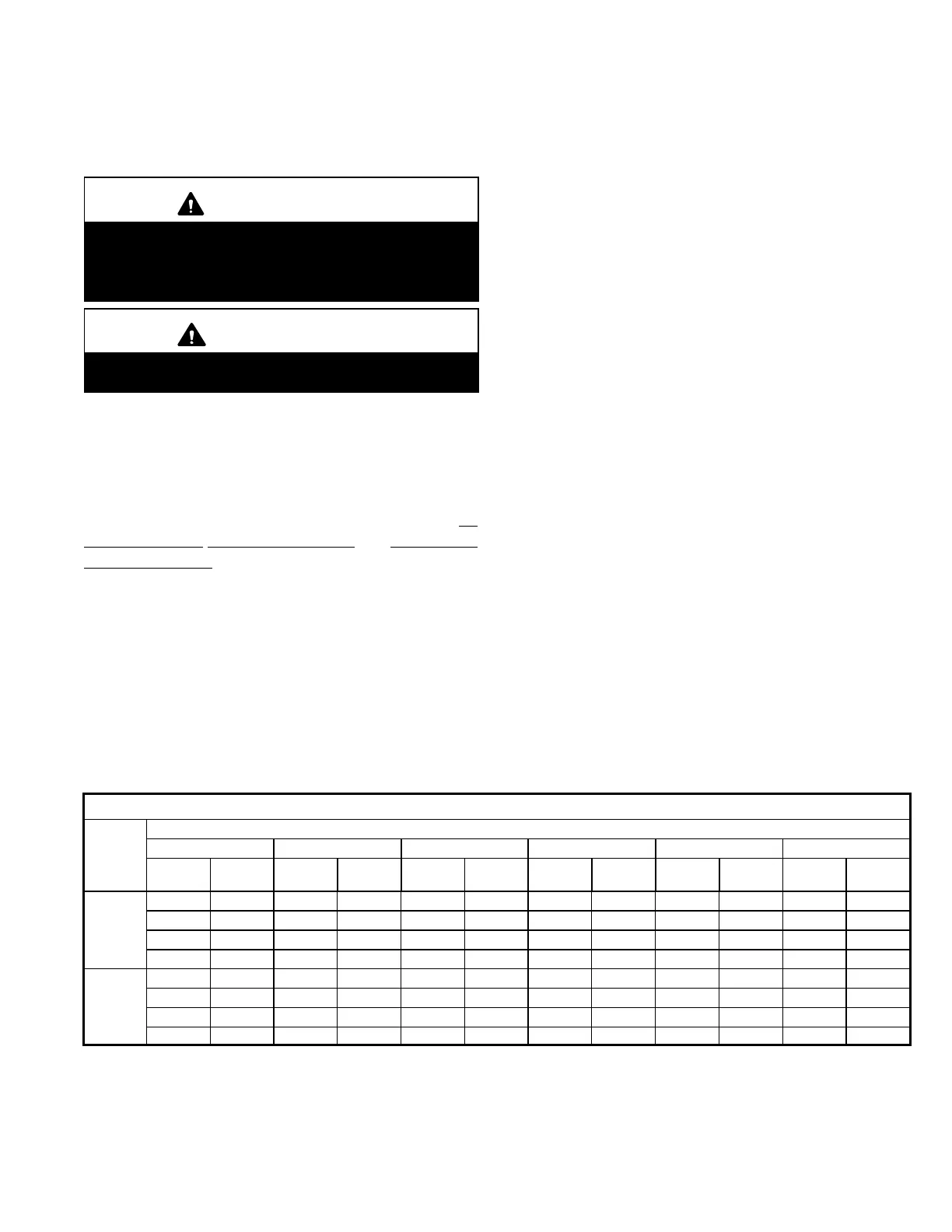
2- Check each system separately with all stages operat
ing. Compare the normal operating pressures (see ta
bles 5 - 8) to the pressures obtained from the gauges.
Check unit components if there are significant differ
ences.
3- Measure the outdoor ambient temperature and the suc
tion pressure. Refer to the appropriate circuit charging
curve to determine a target liquid temperature.
Note - Pressures are listed for sea level applications.
4- Use the same thermometer to accurately measure the
liquid temperature (in the outdoor section).
D If measured liquid temperature is higher than the
target liquid temperature, add refrigerant to the
system.
D If measured liquid temperature is lower than the
target liquid temperature, recover some refrigerant
from the system.
5- Add or remove charge in increments. Allow the system
to stabilize each time refrigerant is added or removed.
6- Continue the process until measured liquid tempera
ture agrees with the target liquid temperature. Do not
go below the target liquid temperature when adjusting
charge. Note that suction pressure can change as
charge is adjusted.
7- Example LGH/LCH092 Circuit 1: At 95°F outdoor am
bient and a measured suction pressure of 130psig, the
target liquid temperature is 96°F. For a measured liquid
temperature of 106°F, add charge in increments until
measured liquid temperature agrees with the target liq
uid temperature.
TABLE 5
LGH/LCH092H Normal Operating Pressures - All-Aluminum - TXV
Outdoor Coil Entering Air Temperature
65 °F 75 °F 85 °F 95 °F 105 °F 115 °F
Suct
(psig)
Disc
(psig)
Suct
(psig)
Disc
(psig)
Suct
(psig)
Disc
(psig)
Suct
(psig)
Disc
(psig)
Suct
(psig)
Disc
(psig)
Suct
(psig)
Disc
(psig)
Circuit 1
110 234 112 273 115 317 116 367 119 428 121 503
118 236 120 275 123 319 125 369 127 426 130 497
136 240 139 278 142 320 145 369 147 422 150 483
157 248 159 284 163 325 166 373 168 424 171 482
Circuit 2
112 232 115 269 117 313 118 371 120 441 122 523
119 237 122 273 125 316 128 367 129 431 132 508
134 243 139 279 143 320 146 370 149 424 151 488
155 253 156 287 161 328 165 376 169 427 172 487
 Loading...