Page 16
I-UNIT COMPONENTS
The LHT unit parts arrangement are shown in figure 1. All
L1, L2, and L3 wiring is color coded; L1 is red, L2 is yellow,
and L3 is blue. See wiring diagrams in the back of this
manual for complete call out of components per LHT unit.
All 7.5 through 12.5 ton units are configure to order units
(CTO).
A-Control Box Components
ELECTROSTATIC DISCHARGE (ESD)
Precautions and Procedures
CAUTION
Electrostatic discharge can affect elec
tronic components. Take precautions
to neutralize electrostatic charge by
touching your hand and tools to metal
prior to handling the control.
LHT control box components are shown in figure 2. The
control box is located in the upper portion of the com
pressor compartment.
1-Disconnect Switch S48 or Circuit Breaker
CB10 (field installed)
LHT units may be equipped with an optional disconnect
switch S48 or circuit breaker CB10. S48 and CB10 are tog
gle switches, which can be used by the service technician
to disconnect power to the unit.
2-Compressor Contactor K1 & K2
All compressor contactors are three‐pole‐double‐break
contactors with a 24VAC coil. In all LHT units, K1 and K2
energize compressors B1 and B2 respectively in response
to first, second or third stage cooling demands. The auxil
iary N.C. contacts are opened to disable the crankcase
heaters when compressor is energized.
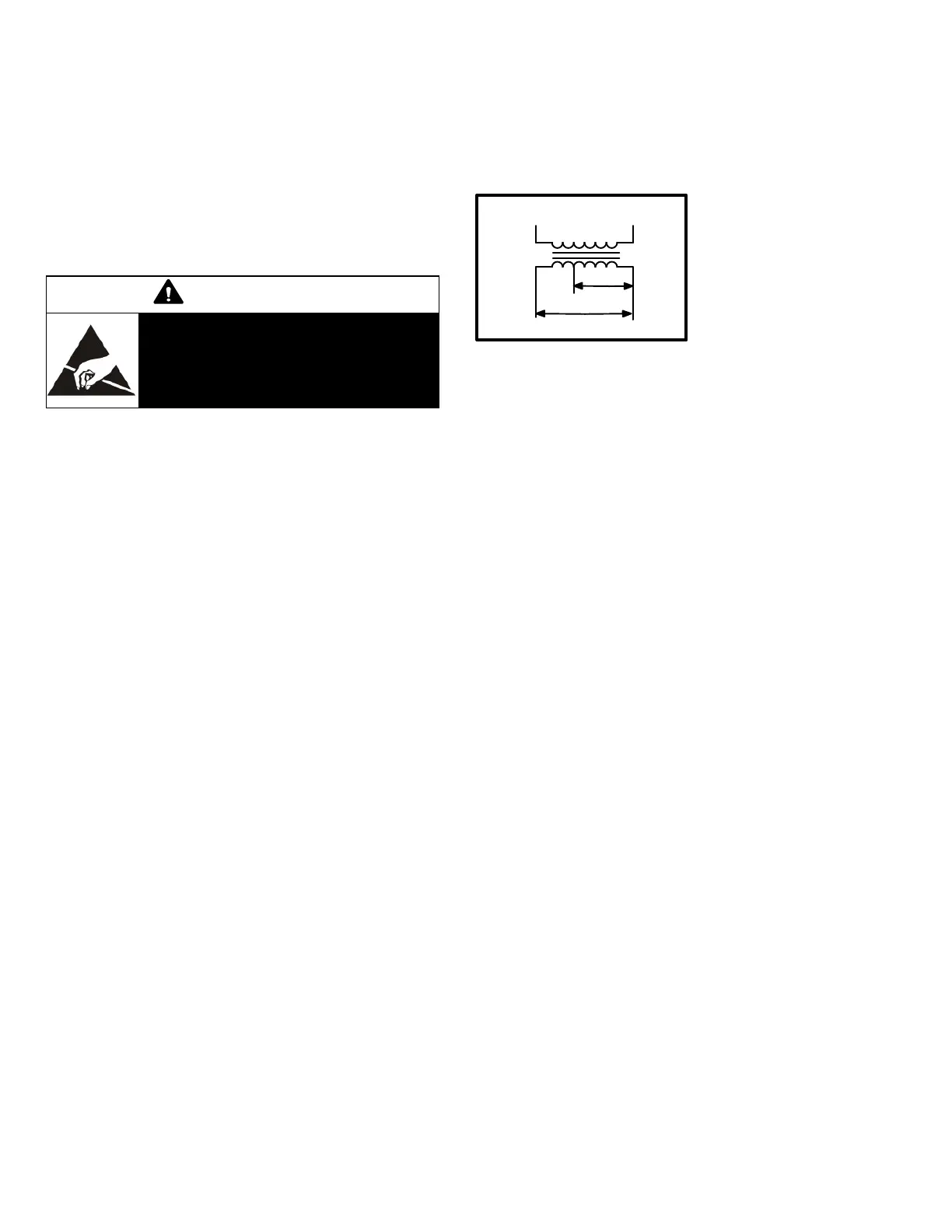
3-Transformer T1
All LHT series units use a single line voltage to 24VAC
transformer mounted in the control box. Transformer sup
plies power to control circuits in the unit. The transformer is
rated at 92VA and is protected by a 6 amp circuit breaker
(CB8). The 208/230 (Y) voltage transformers use two pri
mary voltage taps as
shown in figure 3, while
460 (G) and 575 (J) volt
age transformers use a
single primary voltage
tap.
4-Transformer T18
T18 is a single line voltage to 24VAC transformer used in all
LHT units. T18 is rated at 70VAC and is protected by a 3.5
amp circuit breaker (CB18).
5-Power Exhaust Relay K65 (PED units)
Power exhaust relay K65 is a N.O. DPDT relay with a
24VAC coil. K65 is used in all LHT units equipped with the
optional power exhaust dampers. K65 is energized by the
economizer control panel (A6), after the economizer
dampers reach 50% open (adjustable on control A6).
When K65 closes, the exhaust fan B10 is energized.
6-Terminal Block (TB13)
TB13 terminal block distributes line voltage power to the
line voltage items in the unit.
FIGURE 3
RED
230 VOLTS
208 VOLTS
PRIMARY
SECONDARY
208/230V TRANSFORMER
 Loading...


