Page 14
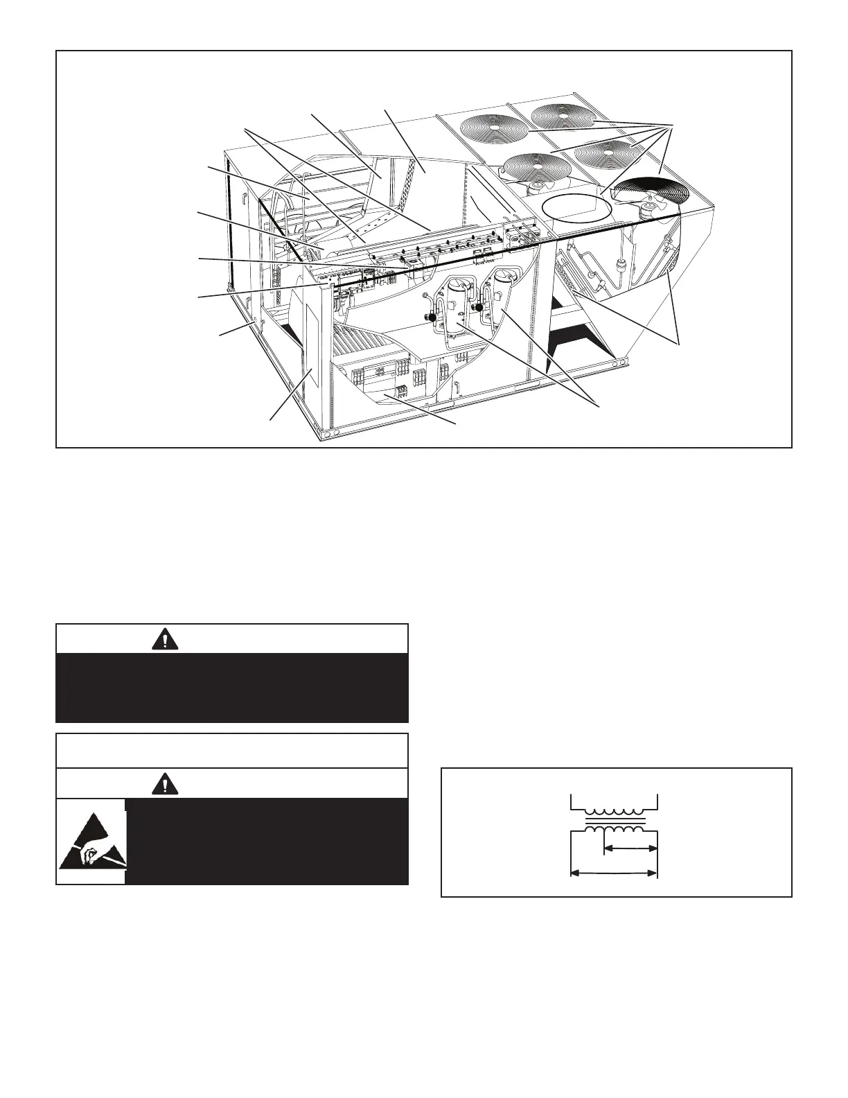
8.8.8.8
ELECTRIC
HEAT
INDOOR
COIL
FILTERS
(SIX - 24 X 24 X 2”)
BLOWER
MOTOR
ECONOMIZER
DAMPERS
(OPTIONAL)
BLOWERS
CONDENSATE
DRAIN
DISCONNECT
(FACTORY-INSTALLED
OPTION)
OUTDOOR
FANS
OUTDOOR
COILS
COMPRESSORS
BLOWER
INVERTER
UNIT
CONTROLLER
FIGURE 1
I-UNIT COMPONENTS
come standard with hinged unit panels. The unit panels
may be held open with the door rod located inside the
is yellow and L3 is blue.
CAUTION
As with any mechanical equipment, contact with
sharp sheet metal edges can result in personal
injury. Take care while handling this equipment and
wear gloves and protective clothing.
ELECTROSTATIC DISCHARGE (ESD)
Precautions and Procedures
CAUTION
electronic components. Take precautions
to neutralize electrostatic charge by
touching your hand and tools to metal
prior to handling the control.
A-Control Box Components
-
sor compartment.
1-Disconnect Switch S48
Units with higher SCCR rating may be equipped with an
-
be used by the service technician to disconnect power to
the unit.
2-Control Transformer T1
All use a single line voltage to 24VAC transformer mount-
-
trol circuits in the unit. The transformer is rated at 70VA
-
age transformers use a single primary voltage tap.
BLUE YELLOW
ORANGE
RED
BLACK
230 VOLTS
208 VOLTS
PRIMARY
SECONDARY
FIGURE 2
3-Contactor Transformer T18
transformer T1. The transformer supplies 24VAC power
to the contactors.
 Loading...


