EasyManuals Logo
Home>Lennox>Heat Pump>LHT Series

Lennox LHT Series User Manual

Lennox LHT Series
48 pages
To Next Page IconTo Next Page
To Previous Page IconTo Previous Page
Page #17 background imageLoading...
Page #17 background image
Page 17
Relative Humidity Sensor - Optional
The indoor relative humidity sensor (A91) is an analog
sensor with a 0-10VDC output over a relative humidity

with 24VAC.
Enthalpy Sensor - Optional
        
the economizer have an output of 4-20mA. The sensor is

󰀨
        
Pressure Transducer (PT5) present in the economizer.
       
-
sponding to 0” water column and 2” water column respec-
tively. For all practical purposes the output should be less
than 1.2” water column if not an error code is stored and
service alarm output is turned on.
Temperature Sensors

and the outdoor air (RT17) are all two wire thermistors.
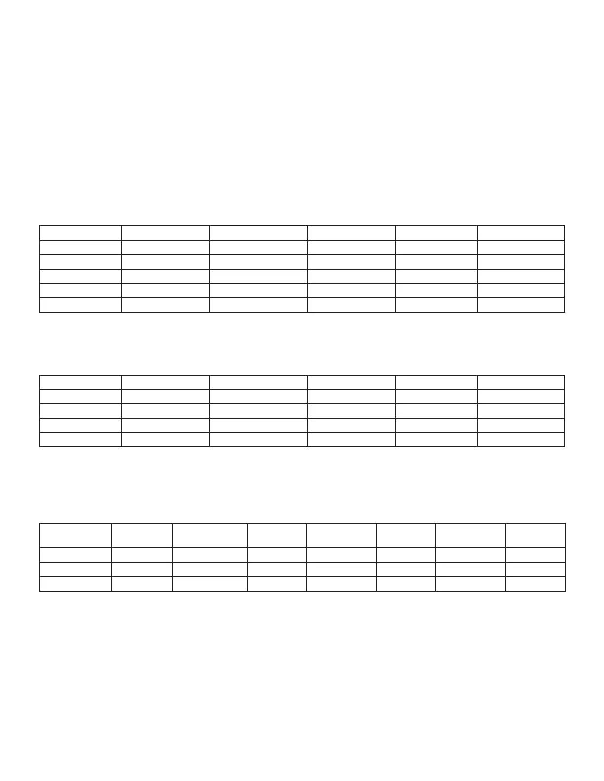

TABLE 1
Resistance vs. Temperature
Temp. °F (°C)  Temperature °F (°C)  Temp. °F (°C) 
-40 (-40)  40 (4.4)  90 (32.2) 
  50 (10)   
     
  70 (21.1)  130 (54.4) 
30 (-1.1)   
Room Sensors
Room sensor (A2) is a two-wire thermistor with 1k series resistor.
TABLE 2
Two-Wire Thermistor
Temp. °F (°C)  Temperature °F (°C)  Temp. °F (°C) 
40 (4.4)     
45 (7.2)     
50 (10)  70 (21.1)  90 (32.2) 
  75 (23.9) 
Carbon Dioxide Sensor

ppm as shown in the following table. The sensor is powered with 24VAC.
TABLE 3
Carbon Dioxide Range

PPM
DC Voltage 
PPM
DC Voltage 
PPM
DC Voltage 
PPM
DC Voltage
0 0  3 1200  9
200 1  4 1400 7 2000 10
400 2 1000 5 

Other manuals for Lennox LHT Series

Questions and Answers:

Question and Answer IconNeed help?

Do you have a question about the Lennox LHT Series and is the answer not in the manual?

Lennox LHT Series Specifications

General IconGeneral
BrandLennox
ModelLHT Series
CategoryHeat Pump
LanguageEnglish

Related product manuals