Page 27
D-OPTIONAL ELECTRIC HEAT
See ELECTRICAL / ELECTRIC HEAT DATA and ELEC-
TRIC HEAT CAPACITIES (table of contents) for LCH to
EHA match-ups and electrical ratings.
All electric heat sections consist of electric heating el-
-
to thermostat demand.
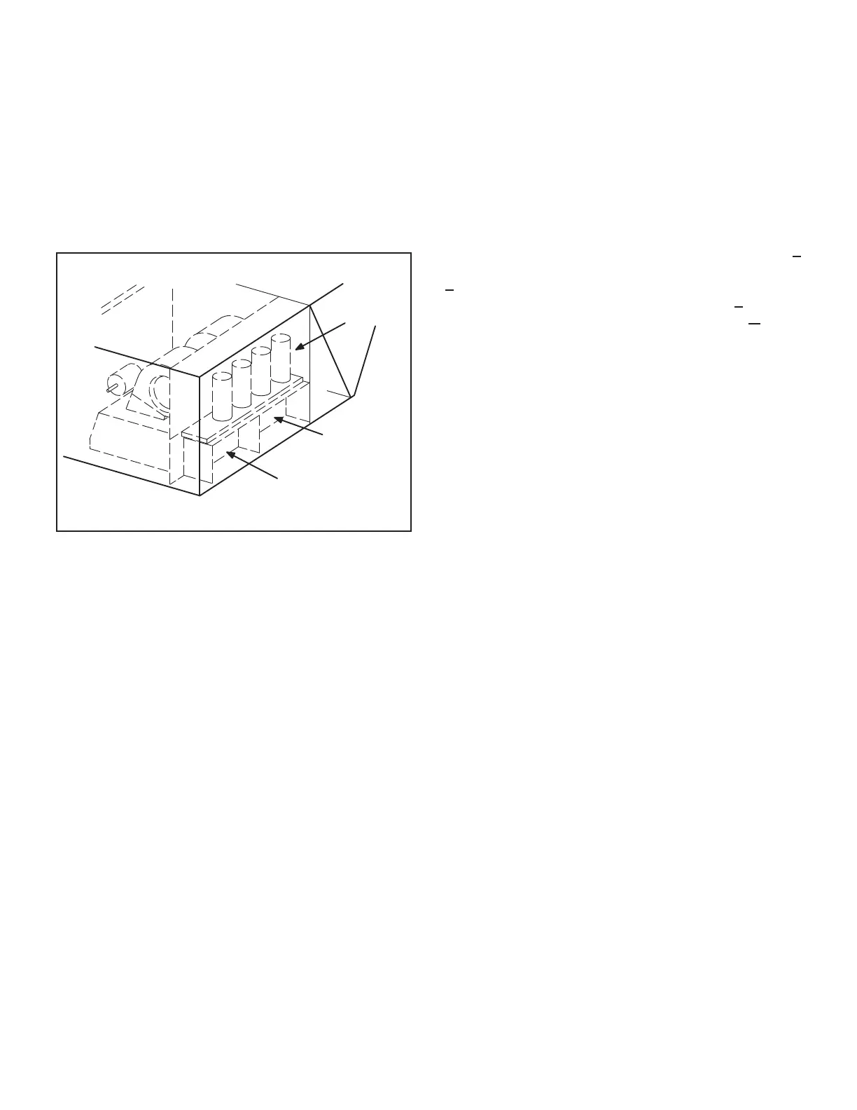
HEAT SECTION PLACEMENT
FIRST ELECTRIC
HEAT SECTION
(LEFT SIDE)
SECOND ELECTRIC
HEAT SECTION
(RIGHT SIDE)
COMPRESSOR
COMPARTMENT
FIGURE 16
1-Main Control Box Components A55, K9
Controller and the K9 electric heat relay.
2-Contactors K15, K16, K17 and K18
-
ble-break contactors located on the electric heat vestibule.
section houses all contactors and fuses. All contactors are
-
stage heating elements.
3-High Temperature Limits S15 and S107 (Primary)
S15 and S107 are SPST N.C. auto-reset thermostats lo-
cated on the back panel of the electric heat section below
the heating elements. S15 is the high temperature limit
temperature limit for the second electric heat section. Both
thermostats are identical and are wired to the A55 Unit
stages of heat are de-energized. The thermostats used
+
+
thermostats are factory set to open at 170 F + 5 F on a
temperature rise and automatically reset at 130 F +
a temperature fall. The thermostats are not adjustable.
4-Terminal Strip TB3
Electric heat line voltage connections are made to termi-
nal strip TB3 (or a fuse block on some models) located in
the upper left corner of the electric heat vestibule.
5-Heating Elements HE1 through HE14
-
-
ments are connected in a three-phase arrangement. The
-
-
ed in “Wye” arrangement.
Each stage is energized independently by the correspond-
ing contactors located on the electric heat vestibule panel.
-
perature protection is provided by primary and redundant
high temperature limits and overcurrent protection is pro-
vided by fuses.
6-Fuse F3
Fuse F3 are housed in a fuse block which holds three fus-
es. Each F3 fuse is connected in series with each leg of
 Loading...


