4 5
1. FITTING THE INSTALLATION PLATE
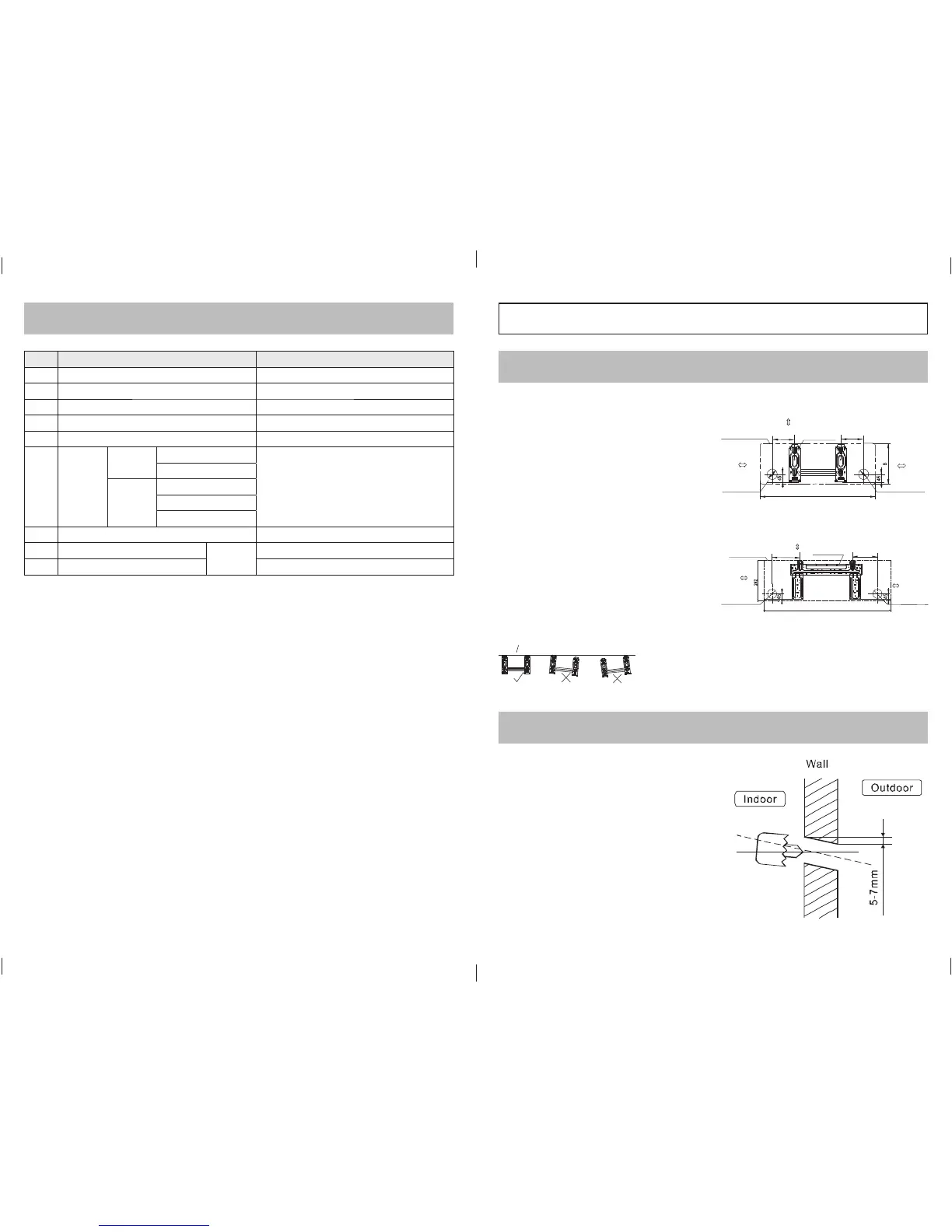
2. DRILL A HOLE IN THE WALL
No. Name of Accessory Quantity supplied
1
Installation Plate 1
2
Clip Anchor 5-8 (depending on models)
3
Self-tapping Screw AST3.9 x 2.5 5-8 (depending on models)
4
Seal (for cooling & heating models only) 1
5
Drain Joint (for cooling & heating models only) 1
6
Connecting
Pipe
assembly
Liquid side
∅6.35
These items must be purchased.
The pipe size differs from appliance to appliance.
Consult the technician for the correct size.
∅9.52
Gas side
∅9.52
∅12.7
∅16
7
Remote controller 1
8
Self-tapping Screw BST 2.9 x 10
Optional
items
2
9
Remote controller holder 1
NOTE: The mounting wall should be strong and solid enough
to prevent it from vibrating.
Fitting the Installation Plate
1. Fit the installation plate horizontally on structural parts of
the wall with spaces around the installation plate.
2. If the wall is made of brick, concrete or similar, drill fi ve
or eight 5mm diameter holes into the wall. Insert clip
anchor for appropriate mounting screws.
3. Fit the installation plate on the wall with fi ve or eight
type-“A” screws.
NOTE: Fit the Installation Plate and drill holes in the wall
according to the wall structure and corresponding mounting
points on the installation plate. The installation plate provided
with the machine differs from appliance to appliance.
(Dimensions are in “mm” unless otherwise stated)
Correct orientation
of Installation Plate
A
Right rear side
refrige rant
pipe h ole 6 5
Inst allation plate
Indoo r unit ou tline
Left rear side
refriger ant
pipe h ole 6 5
15 0 or more to ce i ling
120 or more
to wall
120 or more
to wall
ModelA(A:710,B:250,C:100,D:110)
Model B )(A:790,B:265,C:100,D:150
C
D
150 or mo re to c eiling
Indoor unit outline
Insta llation plate
Right rear side
refriger ant
pipe ho le 65
Left rea r side
refrigerant
pipe ho le 65
12 0 or m ore
to wa ll
120 o r m ore
to wall
920
185
150
Model C
1. Determine hole positions according to left and right side
of the installation plate. The hole centre is obtained by
measuring the distance as shown in the diagram above.
2. Drill the piping plate hole with ∅65mm hole-core drill.
3. Drill the piping hole at either the right or the left and the
hole should be slightly slanted to the outdoor side.
4. Always use wall hole conduit when drilling metal grid,
metal plate or similar.
INDOOR UNIT
SELECT THE BEST LOCATION (continued)
E963_Lennox Split Wall Mounted Installation Manual 12pp A5 1c.indd 4-5E963_Lennox Split Wall Mounted Installation Manual 12pp A5 1c.indd 4-5 9/12/11 11:47 AM9/12/11 11:47 AM
 Loading...