10 11
5. AIR PURGING AND TEST OPERATION
1. Air Purging
• Air and moisture in the refrigerant system have undesirable effects. Therefore the indoor unit and tubing between the
indoor and outdoor unit must be leak tested and evacuated to remove any non-condensables and moisture from the
system.
• Check that each tube (both liquid and gas side tubes) between the indoor and outdoor units have been properly connected
and all wiring for the test run has been completed.
• Pipe length and refrigerant amount:
Connective pipe length Air purging method Additional amount of refrigerant to be charged
Less than 5m Use vacuum pump - -
More than 5m Use vacuum pump Liquid side ∅6.35mm
R22: (pipe length -5) x 30g/m
R410A: (pipe length -5) x 20g/m
Liquid side ∅9.52mm
R22: (pipe length -5) x 60g/m
R410A: (pipe length -5) x 40g/m
• For the R407C refrigerant model, make sure the refrigerant added into the air conditioner is in liquid form.
• When relocating the unit to another place, use a vacuum pump to perform an evacuation.
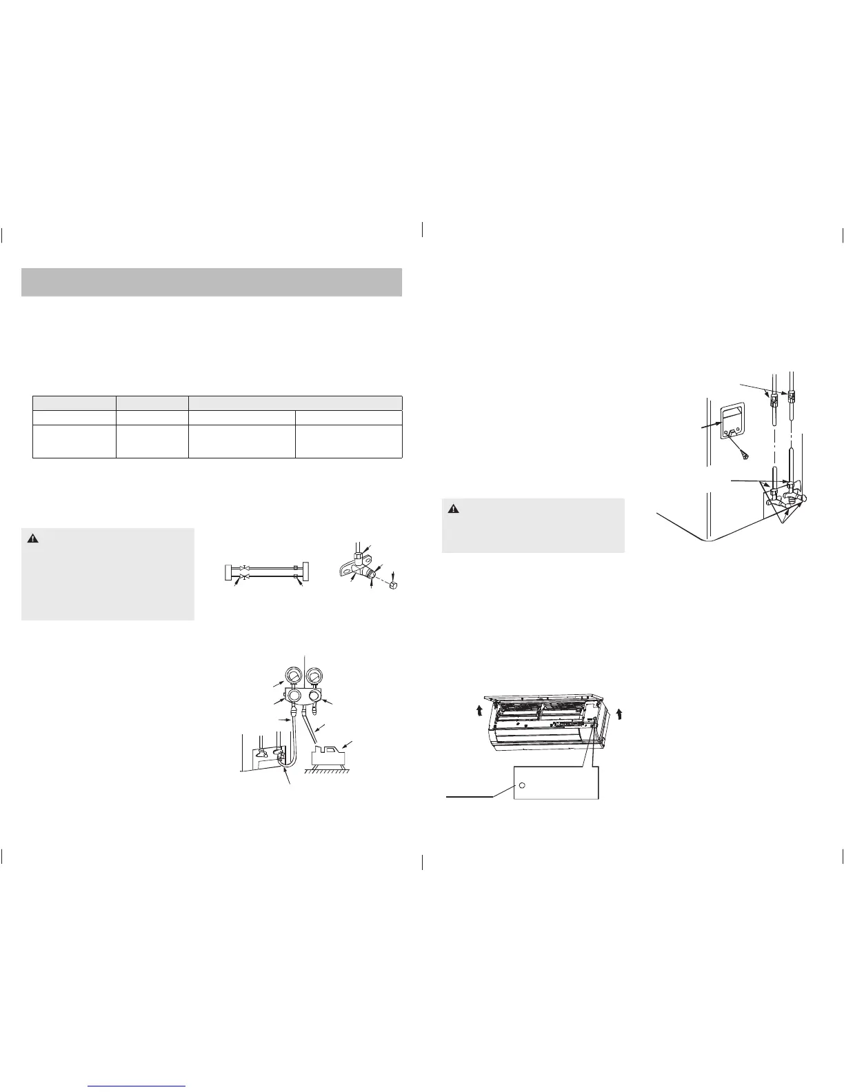
2. When using the Vacuum Pump
1. Completely tighten the fl are nuts A, B, C, D, connect
the manifold valve charge hose to a charge port of the
packed valve on the gas pipe side.
2. Connect the charge hose connection to the vacuum
pump.
3. Fully open the handle Lo of the manifold valve.
4. Operate the vacuum pump to evacuate. After starting
evacuation, slightly loosen the fl are nut of the packed
valve on the gas pipe side and check that the air is
entering. (Operation noise of the vacuum pump changes
and a compound meter indicates 0 instead of minus).
CAUTION
• Open the valve stem until it hits against the
stopper. Do not try to open it further.
• Securely tighten the valve stem cap with a
spanner or the like.
• Valve stem cap tightening torque. See Tightening
torque table (p9).
CAUTION
A: Lo packed valve
B: Hi packed valve C and D are ends of indoor unit
connection.
Flare nut
Stopper
Cap
Valve bo dy
Valv e s tem
Outdoor
unit
Indo or
unit
Refri ge rant
Packe d val ve
Ha lf un ion
Gas side
Liquid side
A
C
D
B
5. After the evacuation is complete, fully close the handle Lo of the manifold valve and stop the operation of the
vacuum pump.
• Evacuate for 15 minutes or until the compound meter indicates -76cmHg (-1.0 x 10
5
Pa).
6. Turn the stem of the packed valve B about 45º counter-clockwise for 6-7 seconds after the gas coming out, then tighten
the fl are nut again. Make sure the pressure display in the pressure indicator is a little higher than the atmospheric
pressure.
7. Fully open the packed valve stems B and A.
8. Securely tighten the cap of the packed valve.
Manifold valve
Compound meter
-76cmHg
Handle Lo
Handle Hi
Charge hose
Charge hose
Vacuum p u mp
Pressure gauge
Packed valve
Indoor unit
check p oint
D
B
C
A
Outdoor unit
check p oint
Cove r
3. Safety and leakage check
1. Soapy water method:
Apply soapy water or a liquid neutral detergent on the
indoor unit connections and outdoor unit connections
by a soft brush to check for leakage of the connecting
points of the piping. If bubbles come out, it indicates that
the pipes have leakage.
2. Leak Detector:
Use the leak detector to check for leakage.
4. Running a preliminary test
Perform a test operation after completing gas leak check at
the fl are nut connections and electrical safety check.
• Check that all tubing and wiring have been properly
connected.
• Check that the gas and liquid side service valves are
fully open.
Manual contro l
button
AU TO/ COO L
1. Connect the power, press the ON/OFF button on the
remote controller to turn the unit on.
2. Use the MODE button to select COOL, HEAT, AUTO and
FAN to check if all the functions work well.
3. When the ambient temperature is too low (lower than
17ºC), the unit cannot be controlled by the remote
controller in the cooling mode – manual operation must
occur. Manual operation is used only when the remote
controller is disabled or maintenance is necessary.
• Hold the panel sides and lift the panel up to an angle
until it remains fi xed with a clicking sound.
• Press the Manual control button to select the AUTO
or COOL, the unit will operate under Forced AUTO or
COOL mode (see User Manual for details).
4. The test operation should last about 30 minutes.
E963_Lennox Split Wall Mounted Installation Manual 12pp A5 1c.indd 10-11E963_Lennox Split Wall Mounted Installation Manual 12pp A5 1c.indd 10-11 9/12/11 11:47 AM9/12/11 11:47 AM
 Loading...