3
• This manual provides the installation instruc-
tions for this controller. Refer to the included
wiring diagrams to connect the controller to
the indoor unit.
• The controller uses low voltage. Keep a mini-
mum distance of 12” (305 mm) between low
voltage control wire and high voltage power
wires.
• Ground the shielded control wiring.
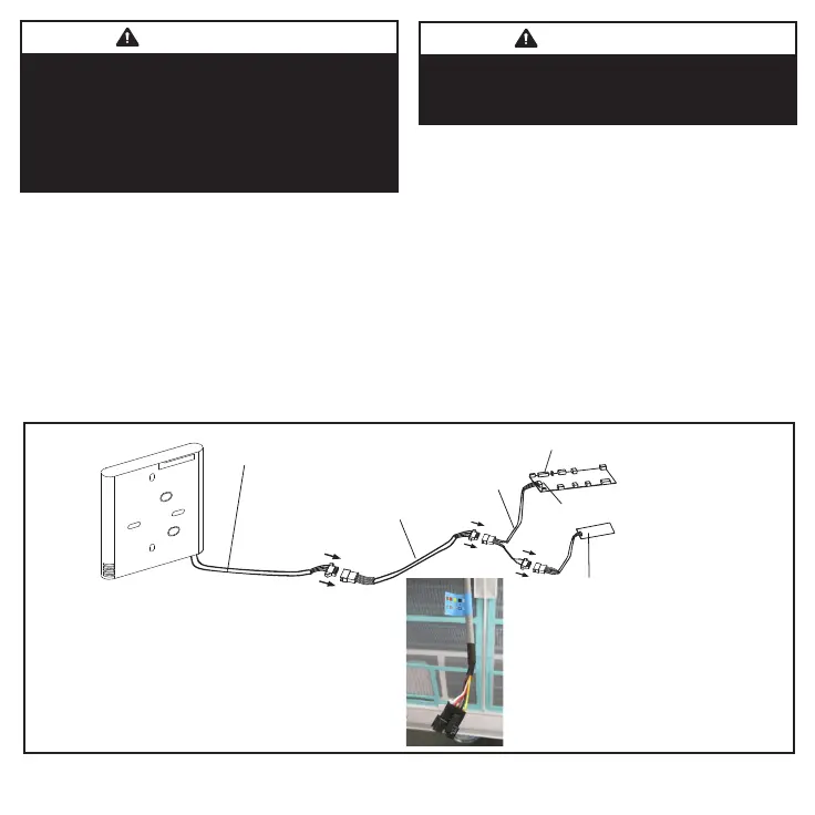
1. Use the wiring connections illustrations (Fig-
ures 2 and 6) to connect the controller to the
indoor unit. NOTE - Connection details for
wall-mounted units differ from the other indoor
unit types.
2. Select the cable exit route from the back of
the controller.
3. Include a drip loop in the cable.
IMPORTANT
Read all of the information in this manual be-
fore using this controller. All wiring must con-
form to local and national building and elec-
trical codes and ordinances. This is a 5 VDC
controller. Do not install on voltages higher
than 5 VDC.
IMPORTANT
The provided cables must be used. Do not
use excessive force while pulling the cable or
when making the connections.
• Do not use a megger to test insulation.
• The controller cable length should not exceed
164 ft (50 m).
Indoor unit main board
Receiver board
Cable A
CN40
Cable B
3 ft. 7 in. (1.1m)
4-conductor shielded
wire on the controller
(Gray cable with blue tag for all units
that require the WYE cable.)
Figure 2. Wiring Connections MMDA/B, MCFA/B, M22A and M33A/B/C

 Loading...