1
PRODIGY
®
2.0
(M3 UNIT CONTROLLER)
APPLICATION GUIDE
507242-03
3/2016
Supersedes 2/2016
WARNING
Improper installation, adjustment, alteration, service or maintenance can cause property damage, personal injury or
loss of life.
Installation and service must be performed by a licensed professional HVAC installer (or equivalent) or service agency.
Table Of Contents
1. Prodigy 2.0 – M3 Unit Controller Description 7...............................................
1.1. Unit Sizes 7.........................................................................
1.2. Add-on Controllers 7..................................................................
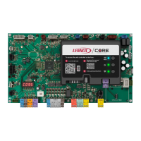
1.3. M3 Unit Controller Layout and Connections 8............................................
2. Main Controller Operation 9.................................................................
2.1. Control Type - Thermostat 9...........................................................
2.1.1. Cooling Stages 9............................................................
2.1.2. Heating Stages 10............................................................
2.2. System Mode - Room Sensor Backup Mode Set Points 11..................................
2.2.1. Network Control Panel 11......................................................
2.2.2. Room Sensor Back-Up Modes 11...............................................
2.2.3. Room Sensor Back-Up Mode Set Points 12......................................
2.2.4. L Connection Network Back-Up Mode Requirements 13............................
2.2.5. Heating and Cooling Stages in Room Sensor Mode 13............................
2.2.5.1. Energence LC/LG -036 through -074U (Ultra-High Efficiency Units) 13......
2.2.5.2. Start-Up Delay in Room Sensor Mode 14...............................
2.2.5.3. Blower Operation (Occupied) in Room Sensor Mode 14..................
2.2.5.4. Room Sensor Parameters 14.........................................
3. Unit Component Operation 16................................................................
3.1. Compressor Protection and Delays 16...................................................
3.1.1. Compressor Minimum Run-Time and Off-Delay 16................................
3.1.1.1. All Energence LC/LG Ultra-High Efficiency Units 16......................
3.1.1.2. All Other Energence Models 16........................................
3.1.2. Compressor On Delay 16......................................................
3.1.3. Freeze-stats (S49, S50, S53 and S95) 16........................................
3.1.4. Thermal Protection Switches (S5, S7, S8, S31 and S180) 16.......................
3.1.4.1. Energence Ultra-High Efficiency Units (3- to 6-ton) 17....................
3.1.4.2. Tandem Compressors — Energence Ultra-High Efficiency Units
(7-1/2 to 12-1/2-ton) 17...............................................
3.1.4.3. Tandem Compressors — Energence Ultra-High Efficiency Units
(15- and 20-ton) 17..................................................
3.1.5. High Pressure Switches (S4, S7, S28 and S96) 17................................
3.1.5.1. Energence Ultra-High Efficiency Units (7-1/2 to 12-1/2 ton) 17.............
3.1.5.2. Energence Ultra-High Efficiency Units (15- and 20-ton)
— Tandem Compressors Units 17......................................






 Loading...