109
24.4. LED Operations
LED Indicators: Some indicators on the circuit board are visible with the cover in place; others are not. The indicators
and their meanings are described in table 62.
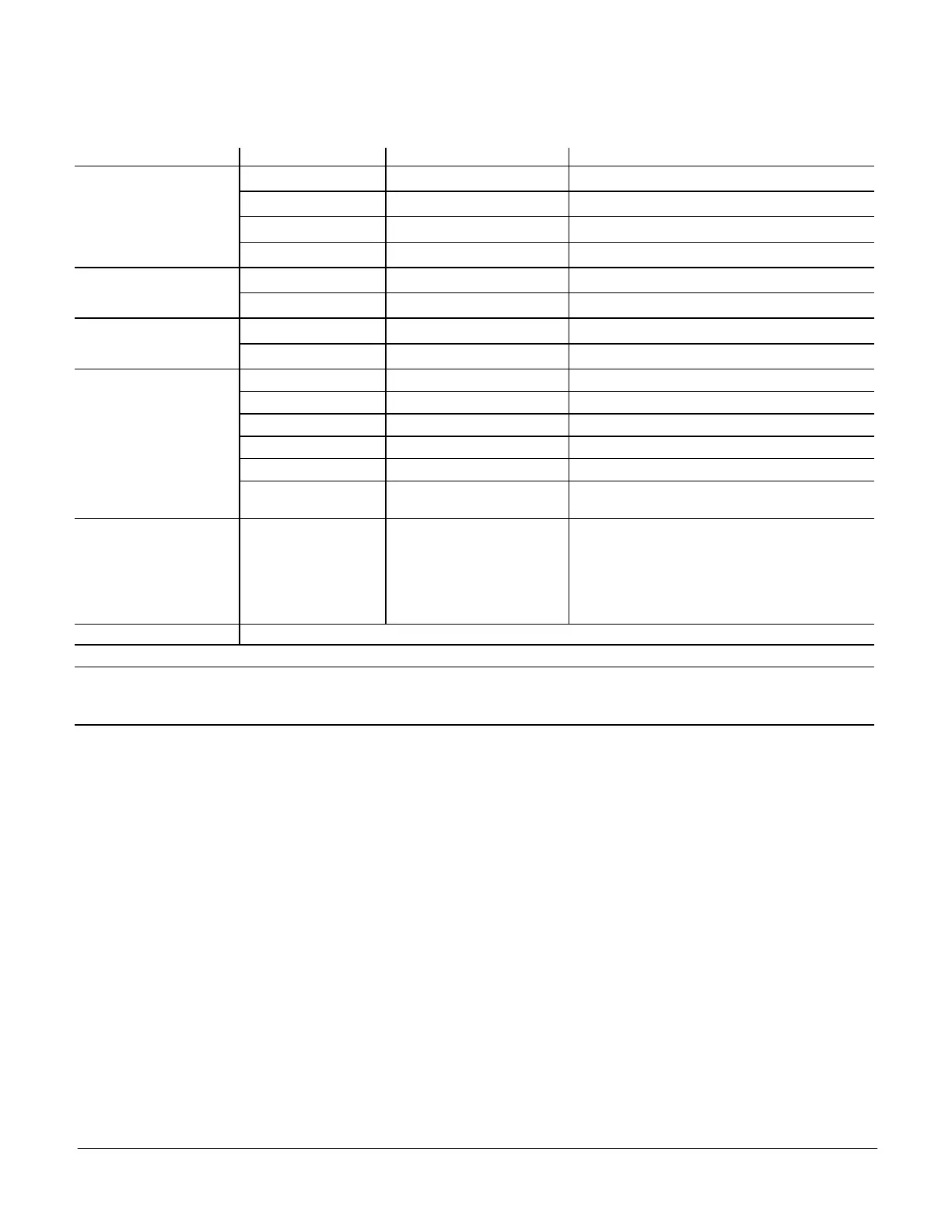
Table 62. LED Operation Indicators
LED Status Indication Meaning
Heartbeat (HB) (D33)
Green Slow Flash Normal Operation
Green Fast Flash Bootloader / firmware update mode
No light Steady Off No voltage to M3 board or defective board
Green Steady On Unit in configuration / test mode (not in normal mode)
S-BUS / PC Connection
(D70 and D71)
BUS (green) Flickering ON Network traffic present
TX (yellow) Flickering ON Unit controller is transmitting
BACnet (option) - LEDs
located on module
RX (green) Flickering ON Unit controller is receiving
TX (yellow) Flickering ON Unit controller is transmitting
LonTalk (option) - LEDs
located on module
RX (green) Flickering ON Unit controller is receiving
TX (yellow) Flickering ON Unit controller is transmitting
SERVICE (red) Flashing 1 sec. on; 1 sec. off Node is not configured; application loaded
SERVICE (UNLIT) Steady off Node is completely configured
SERVICE (red) Constant on Node is configured; no application loaded
SERVICE (red)
Quick flashes during
initialization
Messages being passed to M3; normal operation
Thermostat Input Yellow Indicates a thermostat demand
G - Blower on (D17)
W1 - First-Stage Heating (D20)
W2 - Second -Stage Heating (D23)
Y1 - First-Stage Cooling (D26)
Y2 - Second-Stage Cooling (D29)
OCP - Occupied (D32)
GLO - Global input (D38)
MODBUS Two LEDs that indicate transmit (TX) and receive (RX) activity.
Thermostat LEDs indicate only with incoming thermostat connection via SmartWire connectors.
Slow Flash = 1 second on; 1 second off.
Fast Flash = ½ second on; ½ second off.
A “flickering” LED flashes significantly faster than a “fast flash“.
NOTE: LEDs are energized by 24VAC thermostat inputs.

 Loading...