CONTROLS
KITS AND ACCESSORIES
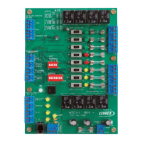
Network Thermostat Controller
NTC1-1- Kit
507796-01
8/2018
Supersedes 11/2017
Installation instructions for Network Thermostat Controller Kits (17M10 and 16H99) used with
Units not Equipped with a Unit Controller
WARNING
Improper installation, adjustment, alteration, service or
maintenance can cause property damage, personal
injury or loss of life.
Installation and service must be performed by a licensed
professional installer (or equivalent) or service agency.
Application
The NTC unit controller is used on units not equipped
with a rooftop unit controller (i.e. [IMC M1−x, M2 or
M3 Prodigy
®
Unit Controller]) to allow access to the L
Connection
®
Network. The NTC may be used to control
rooftop packaged equipment or split systems and is
compatible with the Network Control Panel (NCP) versions
2.00 or later and Unit Controller (UC) software versions
2.08 or later. The NTC can control up to three stages of
cooling, two stages of heating, the blower, and outdoor air
dampers.
Table of Contents
Application ....................................................................1
Shipping and Packing List ...........................................2
Installation .....................................................................2
Roof Top Units .............................................................2
Commercial Split Systems ..........................................3
Heartbeat LED ...............................................................3
Pushbutton ....................................................................3
Manual Output Test Switches ......................................3
Unit Address DIP Switches ..........................................3
Conguration DIP Switches ........................................3
Types of Units - Switches 1 and 2 ...............................3
Number Of Cooling Stages − Switches 3 and 4 ..........4
Number Of Heating Stages − Switches 5 and 6 ..........4
Local or Remote System Mode ...................................4
Local Sensor ...............................................................4
Remote Sensor ...........................................................4
Sensor Back−Up Operation ........................................4
Operation ....................................................................5
Blower Operation ........................................................5
Network Control Panel (NCP) Setpoints .....................5
L Connection Network Setpoints .................................5
Remote Sensor Data Interruption ...............................5
Off Delay .....................................................................5
Discharge Air Control System Mode ..........................6
Operation ....................................................................6
Back−Up Operation .....................................................6
Digital Outputs − P181 and P182 ................................7
Temperature Sensors - P178 .......................................8
Local Zone Sensor A2 .................................................8
Return Air Sensor RT16 ..............................................8
Discharge Air Sensor RT6 ...........................................8
Outdoor Air Sensor RT17 ............................................8
Analog Inputs - P179 ....................................................8
C02 and Relative Humidity Sensor .............................8
Damper Feedback .......................................................8
Digital Inputs - P177 .....................................................8
Air Flow Switch ............................................................8
Service Input ...............................................................8
N.C. Normally Closed Input .........................................8
N.O. Normally Open Input ...........................................9
Check−Out Procedure ..................................................9
Unit Operation .............................................................9
Wiring Between NTC And Unit ....................................9
NTC Operation ............................................................9
Adjustable Parameters.................................................9
Reset NTC Parameters to Default .............................10
Error Codes .................................................................12
Wiring ..........................................................................13
24VAC .......................................................................13
Communication Wiring ..............................................13
Typical NTC1−1 (A113) Field Wiring .........................13
ELA Unit Accessories Wiring Diagram ......................14
General Application (2 Heat and 3 Cool) ...................15
General Application (2 Heat and 3 Cool Heat Pump) 16






 Loading...