Page 9
1
2
3
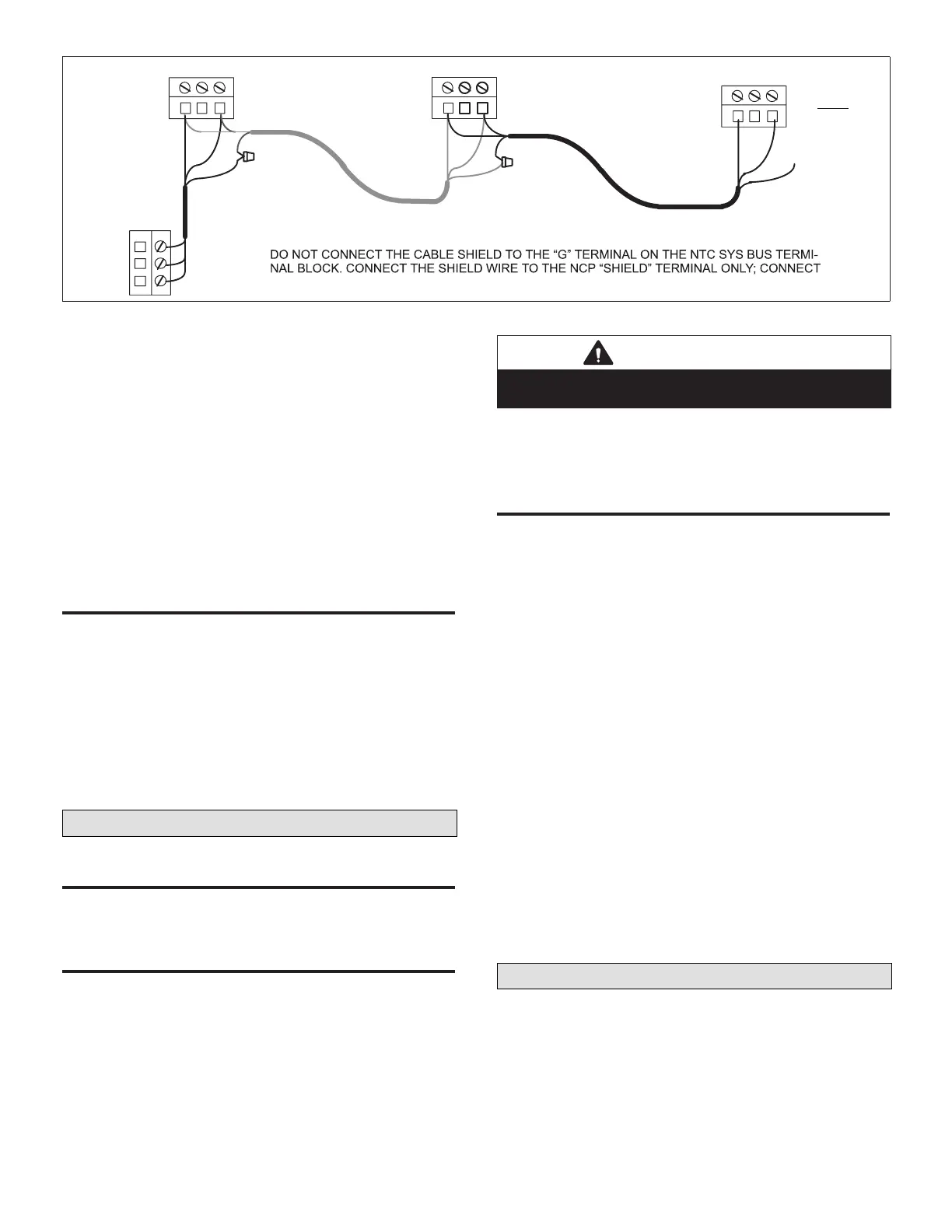
+G −
SYS BUS
ON NCP
SYS BUS
ON NTC
SYS BUS
ON LAST
NTC
+
−
Shield
Shield
Shield
Shield
CONNECT + TERMINALS OF NCP TO + TERMINALS ON THE NTC SYS BUS TERMINAL BLOCK.
CONNECT − TERMINALS OF NCP TO −TERMINALS ON THE NTC SYS BUS TERMINAL BLOCK.
UNIT SHIELD WIRES TOGETHER.
SYS BUS
ON NTC
Figure 11. L Connection Network Daisy−chain Communication Wiring
This input can be used to indicate a blower overload.
Set ECTO A3.04 to option 1. A blower overload must be
installed. If the blower overload trips, the NTC will de−
energize all outputs and issue an alarm code 203 (blower
overload trip). The NTC will retry the input every ve
minutes.
This input can also be used to indicate a loss of phase.
Set A3.04 to option 2. A loss of phase device must be
installed. If the loss of phase device trips, the NTC will
de−energize all outputs and issue an alarm 204 (loss of
phase). The NTC will retry every ve minutes.
NOTE: Connect 24VAC and common wiring to N.C.
terminals when input is not used.
n.o. noRmally open inpUT
The N.O. input is used to de−energize all NTC outputs
when it closes. The NTC will de−energize all outputs and
issue an alarm code 201 (N.O. input is ON). The NTC will
retry every ve minutes.
This input can also be used by a smoke detector. Set
A3.03 to option 1. A smoke detector must be installed.
If the smoke detector trips, the NTC will de−energize all
outputs and issue an alarm code 4 (smoke detector trip).
The NTC will retry every ve minutes.
NOTE: Leave this input open when not used.
Check−Out Procedure
UniT opeRaTion
Use the manual switches to simulate a thermostat demand
and conrm proper unit operation.
wiRing BeTween nTC and UniT
1. Move all manual switches to the OFF position.
2. Apply power to unit.
3. Move the “ G” switch to the ON position to energize the
unit blower.
4. Move the “Y1” switch to the ON position and conrm
the appropriate operation. Move the “Y1” switch to the
OFF position and repeat for each heating and cooling
stage. Proper operation of each function conrms that
the wiring between the NTC and the unit is correct.
IMPORTANT
Do not energize cooling and heating output switches at
the same time
5. Move all switches back to the AUTO position. All
switches must be in the AUTO position to allow the
NTC to control the unit.
nTC opeRaTion
1. Make sure the heartbeat LED is green, energized for
one second and off for one second. This indicates
normal NTC operation. If the LED is green, energized
on for 3 seconds and off for 3 seconds, the NTC is
in an off delay. Press the pushbutton to by−pass the
delay.
2. Make sure the yellow ”XMT” transmit light is blinking.
This indicates that the NTC is transmitting to the
NCP. If the transmit LED is not blinking, make sure
communication wiring connections are correct and
secure and that power is being supplied to the NCP.
NOTE: The transmit LED blinking rate depends on the
number of units connected to the L Connection
bus. The blink rate can be as slow as once every
30 seconds.
3. If an NCP is not connected, the NTC will control the
unit to default settings: 70°F (21°C) heating setpoint,
75°F (24°C) cooling setpoint, and occupied time
period (continuous blower).
4. If the heartbeat is ashing red, the controller is locked
out because of an alarm. Make sure all digital inputs
(P177) are properly connected. The N.C. LED should
be ON. If air ow switch is not used the input must be
jumpered. The service input should normally be OFF
Adjustable Parameters
The NTC default control parameters can be adjusted
using a PC, Unit Controller PC software (version 2.02),
and a PC to L Connection converter.

 Loading...


