Page 13
Wiring
All wiring must comply with local electrical code or as
specied on the unit wiring diagrams. Refer to gure 1
for eld wiring connections. Example wiring diagrams are
provided in the back of this manual.
24VaC
Connect 24VAC power to P176−1 and 2 from a class 2
transformer using standard 18AWG thermostat wiring.
P176−2 (common) must be connected to earth ground.
CommUniCaTion wiRing
Cable type: Lennox P/N 94L63 or 27M19, Belden type
88761 or equivalent. (22AWG stranded or twisted pair,
100% aluminum shield with drain wire, Teon jacket).
Daisy chain the communications cable between each NTC
and NCP as shown in “Figure 11. L Connection Network
Daisy−chain Communication Wiring” on page 9”. Do
not connect the shield drain wire to the NTC “ G”.
NOTE: Make sure the total run of communications wiring
does not exceed 4000 feet (1219 m).
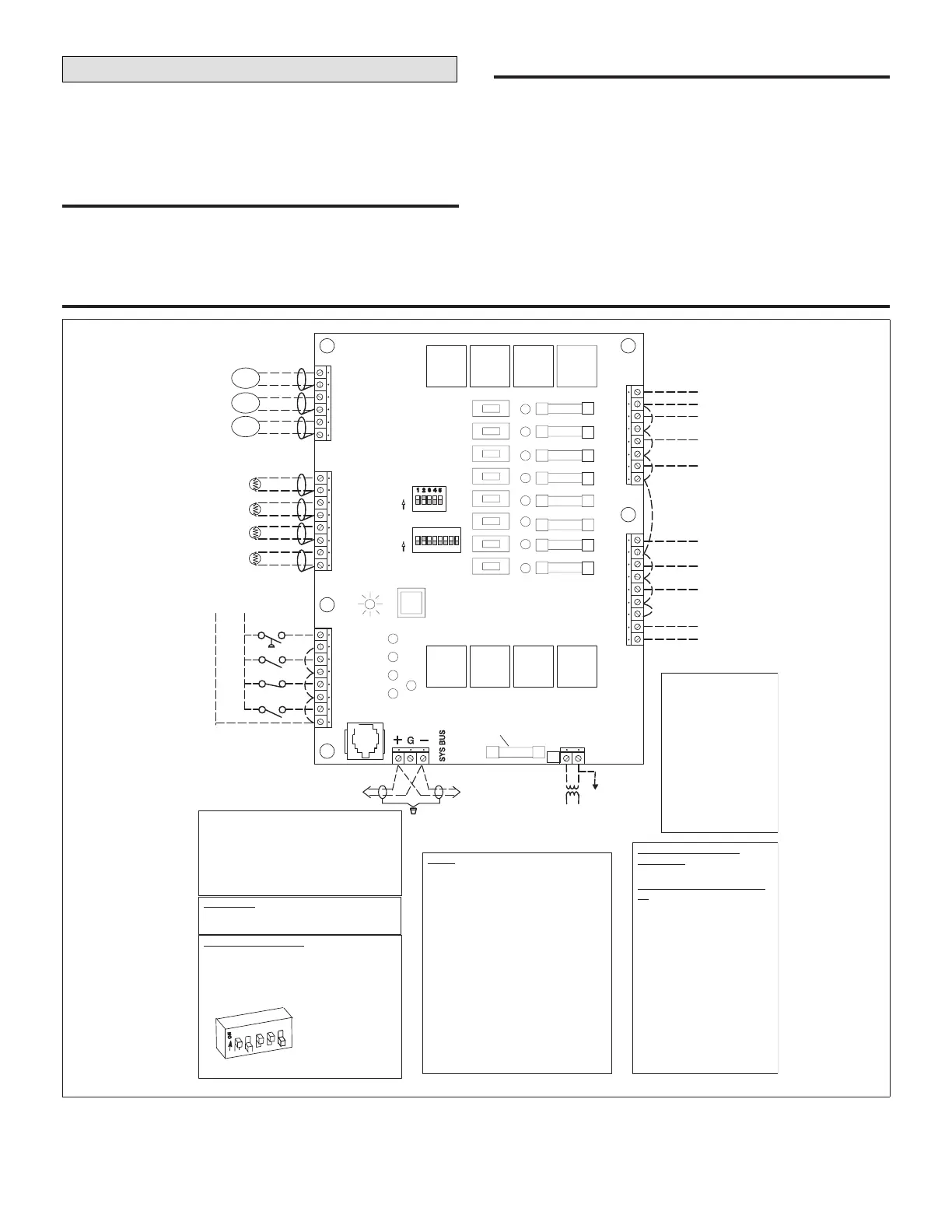
typiCal NtC1−1 (a113) field wiriNg
ZONE
(A2)
RETURN
(RT16)
DISCHARGE
(RT6)
OUTDOOR
(RT17)
CO
2
(0−10VDC)
RH (0−10VDC)
DAMPER FB (2−10VDC)
+
−
+
−
+
−
P179
P178
P177
P181
P182
1
2
3
4
5
6
7
8
+
−
+
−
+
−
+
_
AIR FLOW
SWITCH
SERVICE
N.C.
N.O.
NO
C
NO
C
NO
C
NO
C
Y1
Y2
Y3
W1
NO
C
NO
C
NO
C
C
O
B
W2
G
OCP
HP REVERSING VALVE
HOT
COMMON
POWER IN
CO
2
RH
DMP
Y1
R
Y2
Y3
W1
W2
G
OCP
O
B
COM 24VAC
P181 and P182 outputs are iso-
lated and may be connected to dif-
ferent transformers. Each output
has a 2 amp fuse.
24VAC power input
has a 2 amp fuse.
*
Connect air ow switch
and N.C. terminals to
24VAC and common if not
used. Service switch and
N.O. switch are optional.
All inputs connected to P178
and P179 are optional. See
System Mode sections for
P178 options.
L Connection
communica-
tion bus
GND
24VAC
P176
1
1
1
1
1
1
XMIT
HB
INPUTS OUTPUTS
10VA
MIN.
*
*
SW1
UNIT
ADDRESS
ON
1 2 4 8 16
O
N
12345678
CONFIG
OFF AUTO ON
2A FUSE
P176 Power in − 24VAC
P177 Digital inputs − 24VAC or DC
P178Temperature sensors − thermistor type
P179 Analog inputs − CO2, RH − 0 1− 10VDC,
Damper FB 2−10VDC
P181 Relay outputs − 24V (AC or DC) 2A max
P182 Relay outputs − 24V (AC or DC) 2A max
Conguration DIP SW10
TYPE 12
Electric HEAT OFF OFF
HP Type 1ONOFF
HP Type 2OFF ON
Gas Heat ON ON
COOL 34
1−Stage cool OFFOFF
2−Stage cool ON OFF
3−Stage cool ON ON
HEAT56
No heating OFF OFF
1−Stage heat ON OFF
2−Stage heat OFFON
Temperature Thermistor
Resistance
RT6, RT16
RT17
A2
30°F 34,566
NA
40°F 26,106
NA
50°F 19,904 2
0,904
60°F 15,313 1
6,313
70°F 11,884 1
2,884
80°F 9,2981
0,298
90°F 7,332
8,332
100°F 5,826
NA
All values are +/− 2%.
LED’s
Heartbeat LED:
Green 1 sec. on/o= Normal operation
Green 3 sec. on/o= Delay initiated
Red 1 sec. on/o= No run lock−out
XMIT Transmit LED:
Yellow − = Data is being transmitted
Blink rate varies − as slow as once every 30
seconds when many units are on the network
Digital Input LED’s:
AFS−Yellow steady= Blower is operating
Service−Yellow steady= Indicates the service
input is energized.
N.C.−Yellow steady= Indicates the N.C. input
is energized.
N.O.−Yellow steady=Indicates the N.O. input
is energized.
Thermostat Output LED’s:
Green, red, or yellow steady=Indicates relay is
closed.
Pushbutton
Short push: By−passes on/o delays
Long push: Resets NTC
ADDRESS DIP Switch
Address DIP is used for setting the unit address
when connected to the L Connection network.
Switches add for a total of 31 addresses (1 to 31).
NTC must be reset after changing an address.
EXAMPLE
OF UNIT
ADDRESS 13
1 + 4 + 8 = 13
4
8
16
2
1
Figure 13. Typical NTC1−1 (A113) Field Wiring

 Loading...


