Page 5
opeRaTion
In local or remote sensor mode, default operation, the
NTC controls up to two stages of heating and three stages
of cooling.
The number of stages achieved is dependent on the
conguration DIP switch setting.
Use ECTO stage differential and deadband options to
adjust desired operation.
BloweR opeRaTion
In default operation, the NTC cycles the blower with a
heat/cool demand. ECTO A4.01 can be changed to allow
continuous blower operation.
neTwoRk ConTRol panel (nCp) seTpoinTs
The setpoints can also be adjusted using the optional NCP
Network Control Panel. When an NCP is installed, the
setpoints are determined by the NCP schedule. The NCP
communicates with the NTC via the L Connection network
bus. Internal NTC setpoints are used only if network
communication is interrupted.
l ConneCTion neTwoRk seTpoinTs
The default NTC internal heating and cooling setpoints
are:
• Cooling setpoint: 75°F (ECTO A2.01)
• Heating setpoint: 70°F (ECTO A1.01)
NTC ECTO A1.01 and A2.01 back−up setpoints are used
when the communication link has been lost on the L
Connection system bus. Five minutes after communication
is interrupted, the NTC will reset and start using the back−
up setpoints.
RemoTe sensoR daTa inTeRRUpTion
The NTC will use data from the local sensor if data from
the remote sensor is interrupted or if data is not updated
every ve minutes. An error code will also be recorded. If
a local sensor has failed or is not installed, RT16 is used
as a back−up.
If data is updated while the unit is operating on NTC
internal setpoints, the NTC will immediately use remote
sensor data. The remote sensor update interval should be
two minutes to prevent back−up operation in the event of
a single missed data update.
off delay
In Local or Remote Sensor Mode, the NTC initiates a 2−
minute off delay on any power−up or reset. During the
two minute delay, no blower, heating, or cooling operation
will occur. This delay may be adjusted to stagger the start
of each unit, reducing the initial power demand. (ECTO
A4.06).
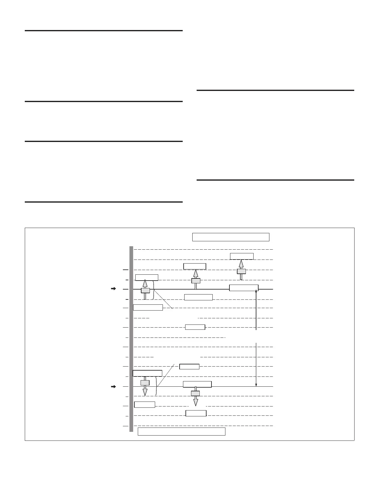
1.0 °F Di.
1.5 °F Di
C2
ON
75°F
Default
Occupied
Cooling
Setpoint
ECTO A2.01
−0.5°F Di
−1.0°F Di.
71
72
73
74
75
76
70
69
68
ON
OFF
OFF
Autochangeover Deadband
Must Be Greater Than ECTO A4.03
70°F
Default
Occupied
Heating
Setpoint
ECTO A1.01
1°F
Cooling Stage Deadband
(All Stages Same Setting)
1°F
Heating Stage Deadband
(All Stages Same Setting)
ECTO A1.04
ON
OFF
0.5 °F Di.
ECTO A2.02
ECTO A2.03
ECTO A2.04
ECTO A1.02
ECTO A1.03
ON
OFF
ON
OFF
−0.5°F
ECTO A2.02−A2.05
0.0 °F
ECTO A2.03−A2.05
0.5 °F
ECTO A2.04−A2.05
0.5
°
F
ECTO A1.02−A1.04
0.0 °F
ECTO A1.03−A1.04
ECTO A2.05
Cooling stage−up timer 15 minutes. ECTO A2.07.
Cooling stage−down timer 15 minutes. ECTO A2.08.
Heating stage−up timer 0 minutes. ECTO A1.06.
Heating stage−down timer 0 minutes. ECTO A1.07.
C1=Cooling Stage 1
C2=Cooling Stage 2
C3=Cooling Stage 3
Units With Economizer:
C1=Free Cooling
C2=Compressor 1
C3=Compressor 2
C1
C3
H1
H2
H1=Heating Stage 1
H2=Heating Stage 2
Figure 8. Local Sensor

 Loading...


