Page 8
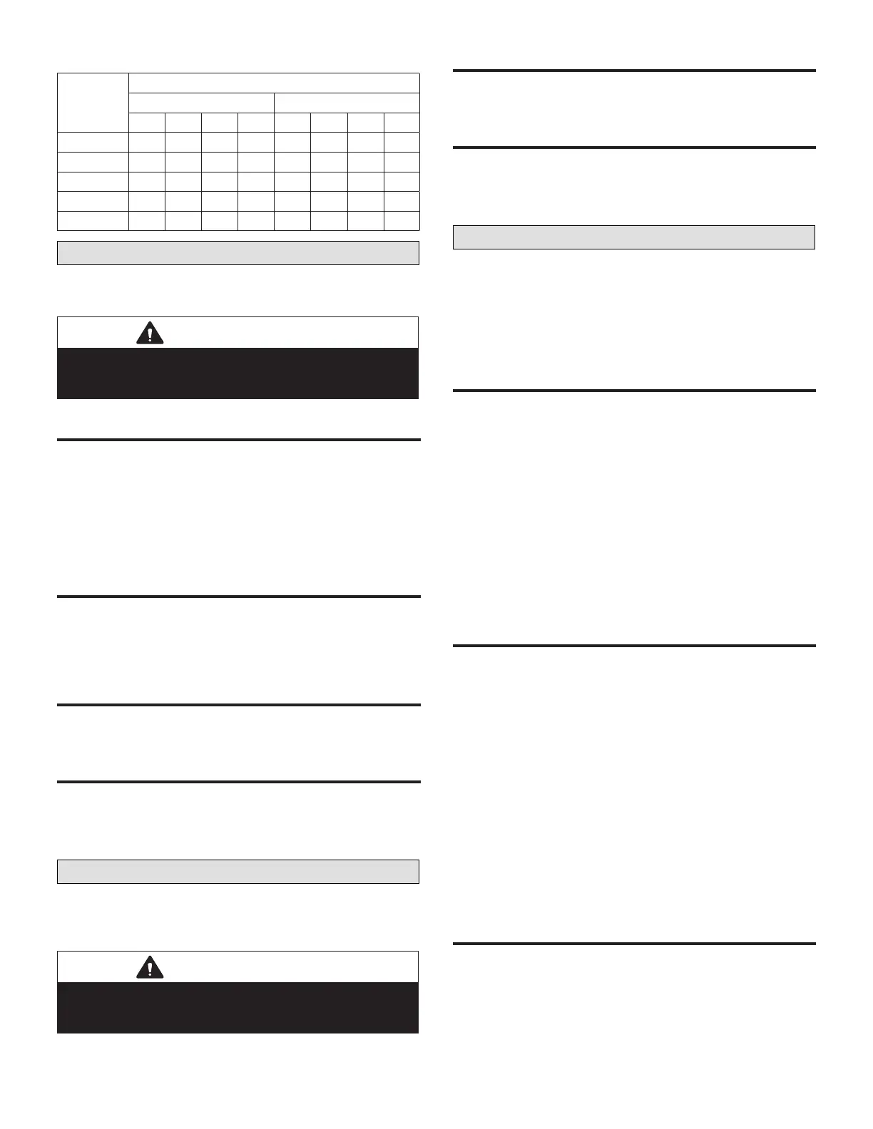
Table 9. Heat Pump Units Type 2
Thermostat
Demand
NTC Digital Output
P181 P182
Y1 Y2 Y3 W1 W2 0 B G
1st Cool ON OFF OFF OFF OFF ON OFF ON
2nd Cool ON ON OFF OFF OFF ON OFF ON
3rd Cool ON ON ON OFF OFF ON OFF ON
Low Heat ON ON ON OFF OFF OFF ON ON
High Heat ON ON ON ON ON OFF ON ON
Temperature Sensors - P178
Sensors are wired to P178 using communication wiring.
Connect the shield drain wire as shown in eld wiring.
IMPORTANT
Make sure any sensors used are compatible with the
L Connection network. Refer to L Connection product
specication (EHB) for part numbers.
loCal Zone sensoR a2
The local zone sensor is required for system operation
unless the NTC is installed:
• In an air handling unit or other appliance which has no
heating or cooling functions.
• With a Zone Link as part of a zoning system.
• With a remote zone sensor.
returN air SeNSOr rt16
The return air sensor is optional and is used to monitor
or to limit heating or cooling. See A1.09, A1.10, A2.10
and A2.11 to set controller for return air temperature limit
option.
diSCharge air SeNSOr rt6
The discharge air sensor is optional and is used to monitor
discharge air temperature.
oUTdooR aiR sensoR RT17
The outdoor air sensor is optional and is used to monitor
outdoor air temperature and to control HP supplemental
heat lock−out and low ambient control. See A1.13, A1.14
and A1.15.
Analog Inputs - P179
Analog inputs are wired to P179 using communication
wiring. Connect the shield drain wire as shown in eld
wiring.
IMPORTANT
Make sure any sensors used are compatible with the
L Connection network. Refer to L Connection product
specication (EHB) for part numbers.
C02 and RelaTive hUmidiTy sensoR
The CO2 and RH sensors are optional and are used for
reporting and displaying to the Network Control Panel only.
dampeR feedBaCk
The Damper FB input is optional and used for reporting
and displaying to the Network Control Panel only. The
input is designed for a 2 to 10 VDC damper feedback
signal; 2 volts = closed and 10 volts = 100% open.
Digital Inputs - P177
Wire digital inputs to P177 using standard 18AWG
thermostat wire.
• Each input is isolated and rated for 24VAC.
• Digital inputs are optional, but air ow switch and n.c.
inputs must be jumpered to 24VAC if not used.
aiR flow swiTCh
The airow switch is used to de−energize heating, cooling,
and blower outputs if there is a loss of blower air.
• The input must be energized within 20 seconds (ECTO
A4.05) of a blower (G) demand or the outputs will be
shut off and the controller will issue an alarm code 5
(airow switch).
• The NTC will retry every ve minutes. After three retries
with no blower air, the controller will lockout and alarm
code 205 will be issued.
• A reset is required after lockout.
NOTE: Connect 24VAC and common wiring to airow
switch terminals when switch is not installed.
seRviCe inpUT
This input is used to indicate the unit may require service.
If the input is energized for longer than one minute
(ECTO A3.01), the controller will issue an alarm code 200
(service). This alarm is for information only and does not
interrupt operation.
• The input can be used to indicate a dirty lter.
• Set ECTO A3.01 to option 1.
• A dirty lter switch must be installed.
• If the dirty lter switch is on for one minute (ECTO
A3.01), the controller will issue an alarm code 6 (dirty
lter).
• This alarm is for information only and does not interrupt
operation.
NOTE: Leave this input open when not used.
n.C. noRmally Closed inpUT
The N.C. input is used to de−energize all NTC outputs
when it opens. The NTC will de−energize all outputs and
issue an alarm code 202 (N.C. input is OFF). The NTC will
retry the input every ve minutes.

 Loading...


