2
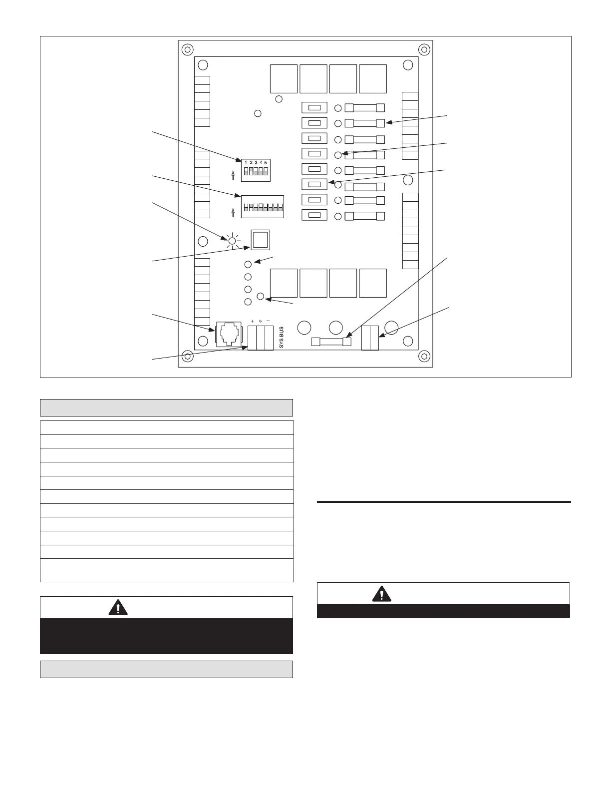
SW1
UNIT
ADDRESS
ON
1 2 4 8 16
ON
CONFIG
UNIT ADDRESS
DIP SWITCHES
CONFIGURATION
DIP SWITCHES
HEARTBEAT LED
PUSHBUTTON
L CONNECTION
COMMUNICATION
JACK
L CONNECTION
COMMUNICATION
FUSES (8)
2 AMP/250V/5X20mm
THERMOSTAT OUTPUT
LED’S (8)
MANUAL OUTPUT TES
SWITCHES (8)
24VAC POWER FUSE
(2 AMP/250V/5X20mm)
24VAC POWER
CONNECTOR
OFF AUTOON
Y1
Y2
Y3
W1
W2
G
OCP
B
XMIT LED
DIGITAL INPUT LED’S (4)
123 45678
Figure 1. NTC1 Network Thermostat Controller
Shipping and Packing List
17M10 (LB−100354 ) package 1 of 1 contains:
• NTC1-1 controller (A113) version 1.1x assembly (1)
• Installation instruction (1)
• Bag which contains#6 − 32X1/2” TFS screws (4)
16H99 (618383-01) package 1 of 1 contains:
• Control box (1)
• Control box cover (1)
• Installation instruction (1)
• #10-16 X 5/8 SMS screws (6)
• Bushing (snap) (2)
• Bag which contains wire tie (2), #6-32 X 1/2 and HWHTFS screws
(4)
CAUTION
Danger of sharp metallic edges. Can cause injury. Take
care when servicing unit to avoid accidental contact with
sharp edges.
Installation
Install the NTC1−1 panel inside the unit if space is
available. Install in a remote location no further than 100
feet from the unit. Installation site must be dry and free of
harmful vapors and gases.
Make sure there is space for the wiring and the controller
is accessible for servicing.
• Rooftop Units: If required, an optional rainproof NEMA
hinged enclosure is available
• Commercial Split Systems: Enclosure and cover are
provided in the kit.
Roof Top UniTs
1. Disconnect all electrical power to unit.
2. Use NTC1 baseplate as template to mark location
of four mounting holes at desired installation site
(see “Figure 2. NTC1 Network Thermostat Controller
(A113) Mounting Hole Locations”). The NTC1−1 may
be installed in any direction.
IMPORTANT
Do not remove the NTC1−1 baseplate.
3. Drill holes and secure NTC1 in place with four screws
provided in kit.

 Loading...


