Page 6
Discharge Air Control System Mode
opeRaTion
The NTC will operate in Discharge Air Control (DAC)
system mode only when used with a Lennox Zone Link as
part of a zoning system. Refer to the Zone Link installation
instruction.
Set ECTO 4.07 to option 2 to initiate Discharge Air Control
system mode. Discharge Air Control Cooling (DACC)
allows the NTC to automatically cycle up to three stages
of cooling. Discharge Air Control Heating (DACH) allows
the NTC to automatically cycle up to two stages of heating.
An additional thermostat or Energy Management System
is not required.
When an economizer is installed, adjust free cooling
setpoint approximately two degrees lower than DACC
setpoint.
This will allow free cooling to operate before DACC
energizes compressors.
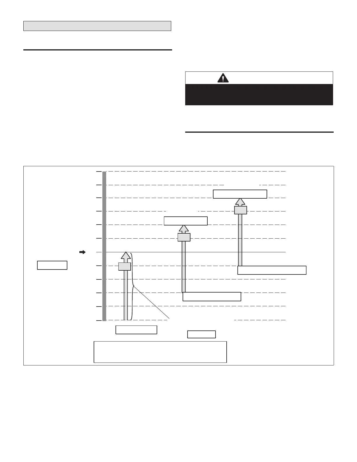
Refer to “Figure 9. Discharge Air Control Cooling (DACC)
Stages − Default Values Shown” for DACC cooling stages.
Refer to “Figure 10. Discharge Air Control Heating (DACH)
Stages − Default Values Shown” on page 7for DACH
heating stages.
IMPORTANT
Field−provided discharge air sensor RT6 must be
installed in the supply air duct, preferably after a 90
degree branch of the main duct.
DAC is initiated by an L Connection Network command.
baCk−up OperatiON
Optional return air sensor RT16 is used as a back−up if
the SysBus connection fails.
If RT6 discharge air sensor fails or is not connected, unit
heating and cooling operation stops.
56
57
58
59
60
55
54
53
55°F
Default Occupied
DACC Setpoint
C1
ON
OFF
55°F − 5°F
ECTO A4.13−A4.14
A4.15 DAC Cooling S tage−Up Delay 3 minutes
A4.16 DAC Cooling S tage−Down Delay 2 minutes
Compressor Minimum Run Times Apply
52
51
50
5°F
DACC Deadband
(All Stages Same Setting)
C2
ON
OFF
55°F + 2 °F Di
ECTO A4.13+ A4.17
55°F + 2 °F − 5°F
ECTO A4.13 + A4.17 − A4.14
ON
OFF
55°F + 4 °F Di.
ECTO A4.13 + (A4.17 x 2)
C3
55°F + (2 °F X 2) −5 °F
ECTO A4.13 + (A4.17 x 2) − A4.14
ECTO A4.14
ECTO A4.13
2=Cooling Stage 2
3=Cooling Stage 3
Figure 9. Discharge Air Control Cooling (DACC) Stages − Default Values Shown

 Loading...


