12
IMPORTANT
Do not over-tighten a ared joint. Flared connections should always be accessible and must be insulated to prevent
condensation.
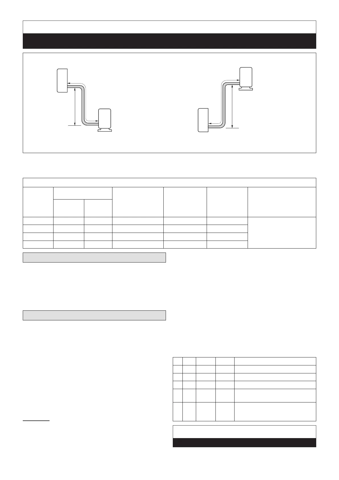
OUTDOOR UNIT
OUTDOOR UNIT
INDOOR UNIT
INDOOR UNIT
Maximum Line Set
Length
Maximum Line Set
Length
Maximum
Elevation -
Outdooor
Unit BELOW
Indoor Unit
Maximum
Elevation -
Outdooor
Unit ABOVE
Indoor Unit
Minimum Line Set
Length - 10 ft. (3m)
Minimum Line Set
Length - 10 ft. (3m)
Outside Unit BELOW Indoor Unit Outside Unit ABOVE Indoor Unit
Figure 26. Indoor and Outdoor Unit Elevation Relationships
Table 5. Line Set Guide
Each system size has a line set length and vertical elevation parameters.
System
Size (KBtu)
Line Set Diameters (in.)
Maximum Elevation
Outdoor Unit BELOW
Indoor Unit - Feet
(Meter)
Maximum
Elevation
Outdoor Unit
ABOVE Indoor
Unit - Feet (Meter)
Maximum Line
Set Length -
Feet (Meters)
Additional Refrigerant for
greater than 25 Foot Line Set
Lenght
Liquid Gas
009 1/4 3/8 82 (25) 33 (10) 82 (25)
For the additional charging, we
recommend 0.161 oz. for 1/4”
liquid line and 0.322 oz. for 3/8”
liquid line per foot.
012 1/4 1/2 82 (25) 33 (10) 82 (25)
018 1/4 1/2 98 (30) 66 (20) 98 (30)
024 3/8 5/8 98 (30) 66 (20) 98 (30)
Adding Refrigerant for Longer Line Set
The outdoor unit is factory-charged with refrigerant
to accommodate up to 25 feet of line set. For adding
additional refrigerant for longer line sets, see “Table 5.
Line Set Guide”.
Be sure to add the proper amount of additional refrigerant.
Failure to do so may result in reduced performance.
Leak Test and Evacuation
Air and moisture remaining in the refrigerant system will
have undesirable effects as indicated below:
• Pressure in the system rises.
• Operating current rises.
• Cooling or heating efciency drops.
• Moisture in the refrigerant circuit may freeze.
• Water may lead to corrosion of parts in the refrigera-
tion system.
The line set between the indoor and outdoor units
must be leak tested and evacuated to remove any non-
condensables and moisture from the system.
Leak Test
Use the following procedure to test for system leaks:
1. Connect the manifold gauge set and dry nitrogen gas
cylinder to the suction and gas service ports.
2. Open valve on nitrogen cylinder.
3. Pressurize the system per the pressure test
specications in “Table 6. Pressure Test
Specications”.
4. Check that the system pressure remains stable. If
there is any movement check system for leaks.
5. After the system is found to be free of leaks:
• Close valve on nitrogen cylinder.
• Relieve the nitrogen pressure by: loosening the
charge hose connector at the nitrogen cylinder.
• When the system pressure is reduced to normal,
disconnect the hose from the cylinder.
Table 6. Pressure Test Specications
Bar Psig kPa Duration
1 3 44 303 Minimum of 10 minutes
2 15 220 1517 Minimum of 10 minutes
3 32 470 3241 Minimum of 10 minutes
4 45 650 4482
1 hour. Stress test to prove the
integrity of the complete installation.
5 32 470 3241
24 hours. Lower system pressure
test, after conrmation No. 4 was
successfully completed.
IMPORTANT
Use only oxygen-free nitrogen (OFN).
 Loading...