 Loading...
Do you have a question about the Lennox MMDB and is the answer not in the manual?
| Brand | Lennox |
|---|---|
| Model | MMDB |
| Category | Air Conditioner |
| Language | English |
Identifies model number components for M22A/M33C cassette indoor units.
Technical specifications for the M22A cassette non-ducted indoor unit.
Technical specifications for the M33C cassette non-ducted indoor unit.
Provides dimensional drawings and measurements for the M22A indoor unit.
Provides dimensional drawings and measurements for the M33C indoor unit.
Specifies minimum clearance requirements for M22A/M33C indoor units.
Locates and explains control board switches for M22A/M33C units.
Step-by-step procedure to test condensate drain functionality for M22A/M33C units.
Explains the model number structure for MMDB ducted indoor units.
Lists technical specifications for MMDB ducted indoor units.
Presents air volume and external static pressure data for MMDB units.
Provides dimensional drawings and measurements for MMDB ducted units.
Specifies clearance requirements for MMDB ducted indoor units.
Details condensate pump lift capabilities for MMDB, M22A/M33C units.
Procedure to test condensate drain functionality for MMDB units.
Information on gravity drain setup for MMDB indoor units.
Explains model number structure for MWMC and 3WMC wall-mounted units.
Technical specs for MWMC/3WMC units (009-012 Ton).
Technical specs for MWMC/3WMC units (018-030 Ton).
Technical specifications for the 3WMC indoor unit.
Provides dimensional drawings for MWMC and 3WMC indoor units.
Specifies clearance requirements for MWMC/3WMC units.
Locates and explains control board switches for MWMC/3WMC units.
Details the procedure and sequence for dry mode operation.
Instructions for performing a test run on MWMC/3WMC units.
Guidance on re-checking pipe connections after initial setup.
Operation guidance when ambient temp is low.
Explains the model number structure for MCFA/MCFB units.
Technical specifications for MCFA/MCFB units (018-048 Ton).
Provides dimensional drawings for MCFA/MCFB indoor units.
Specifies clearance requirements for MCFA/MCFB indoor units.
Locates and explains control board switches for MCFA/MCFB units.
Explains the model number structure for MFMA floor units.
Technical specifications for the MFMA 012 Ton floor unit.
Provides dimensional drawings for MFMA floor indoor units.
Specifies clearance requirements for MFMA floor indoor units.
General overview of power and communication wiring for systems.
Provides guidance on wiring types and gauges for systems.
Illustrates terminal connections for single and multi-zone systems.
Information on the 22U49 wireless remote for MWMC/3WMC units.
Information on the 22U50 wireless remote for M22A/MFMA/MCFA/MCFB units.
Information on the 22U52 wireless remote for M33C units.
Information on wired remotes for MMDB units.
How to set indoor unit addresses for centralized control systems.
Details on connecting to centralized controllers via XYZ terminals.
Connecting external devices for unit ON/OFF control.
Connecting alarm devices to indoor units.
Specifications for connecting cables and wire gauges.
Explains model number structure for single/multi-zone outdoor units.
Technical specs for MPC single-zone units (0.75-1.5 Ton).
Technical specs for MPC single-zone units (2-4 Ton).
Technical specifications for 3PC single-zone units.
Technical specs for MLB single-zone units (0.75-2 Ton).
Technical specs for MLB single-zone units (3-4 Ton).
Technical specs for MPC multi-zone units (1.5-2.5 Ton).
Technical specs for MPC multi-zone units (3-4 Ton).
Technical specs for MLB multi-zone units (1.5-3 Ton).
Technical specs for MLB multi-zone units (4 Ton).
Provides dimensional drawings for single-zone outdoor units.
Provides dimensional drawings for multi-zone outdoor units.
Specifies clearance requirements for outdoor units.
Lists valid indoor/outdoor unit combinations for MPC multi-zone systems.
Lists valid indoor/outdoor unit combinations for MLB multi-zone systems.
Refrigerant cycle diagram for MPC/3PC single-zone systems.
Refrigerant cycle diagram for MPC two-zone systems.
Refrigerant cycle diagram for MPC three-zone systems.
Refrigerant cycle diagram for MPC four-zone systems.
Refrigerant cycle diagram for MPC five-zone systems.
Refrigerant cycle diagram for MLB six-zone systems.
Specifies piping length and elevation limits for single-zone systems.
Specifies piping length and elevation limits for multi-zone systems.
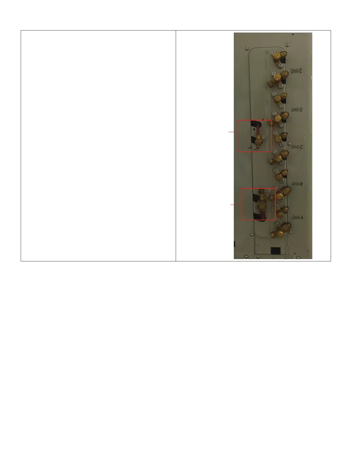
Explains that master valves control refrigerant to all zone-supply valves.
Instructs to open master valves before zone-supply valves.
Lists connection sizes for MPC018S4M outdoor unit with indoor units.
Lists connection sizes for MPC024S4M outdoor unit with indoor units.
Lists connection sizes for MPC030S4M outdoor unit with indoor units.
Lists connection sizes for MLB018S4M outdoor unit with indoor units.
Lists connection sizes for MLB030S4M outdoor unit with indoor units.
Lists connection sizes for MLB036S4M outdoor unit with indoor units.
General overview of power and communication wiring requirements.
Details how to connect condensate drain for outdoor units.
Wiring diagrams for MPC condensate pumps.
Specifies torque values for refrigerant pipe connections.
Details maximum piping length and elevation differences.
Guidance on calculating additional refrigerant charge based on pipe length.
Procedure for checking refrigerant lines for leaks.
Steps for purging air from the refrigeration system.
Procedure for adding refrigerant for extended pipe runs.
Procedure for adding refrigerant after extended system shutdown.
Steps for servicing the indoor unit refrigeration circuit.
Procedures for evacuating the refrigeration circuit after service.
Glossary of electronic function abbreviations used in the manual.
Electrical specifications for control systems.
Procedure for adding refrigerant to single-zone systems.
Procedure for adding refrigerant to multi-zone systems.
Identifies the location of LEDs on single-zone outdoor unit main boards.
Identifies LEDs and SW1 switch locations on multi-zone outdoor units.
Lists and defines abbreviations for electronic functions.
Details electrical parameters for control systems.
Outlines main protection features for the compressor.
Describes communication failure protection mechanisms.
Explains compressor preheating functions and conditions.
Details compressor crankcase heater operation.
Provides cooling charge pressure charts based on temperatures.
Provides heating charge pressure charts based on temperatures.
Displays pressure readings in PSI for heating mode.
Formula and method for calculating system capacity requests.
Explains the conditions and logic for initiating defrost mode.
Theoretical basis for defrost mode activation.
Conditions that cause the unit to exit defrost mode.
Describes how outdoor fan speed is controlled based on ambient temperature.
Outdoor fan speed control logic for cooling mode.
Outdoor fan speed control logic for heating mode.
Explains four-way valve operation in different modes.
Details the operation and control of EXVs.
EXV control logic for cooling mode operation.
EXV control logic for heating mode operation.