73
DC MOTOR
DRIVER MODULE
CN13
CN3
3
CN15
5
M
CN6
T2
T1
4
BLACK
WHITE
INDOOR UNIT MAINBOARD
CN3
RED
CN2
CN1
Y/G
BL ACK
CN41
YELLOW
CN5
WATER LEVEL SWITCH
Reactor
CN8
CN18
RED
RED
• • • • •
This symbol indicates the element is
optional,the actual shape shall prevail.
CN19
BLUE
BLACK
To CCM
Comm.B us
WHITE
X Y
E
Y/G
1
2 3
FILTER-BOARD
BLACK
RED
CN23
ON/OFF
CN33
ALA RM
Alarm
Output
Remote
Control
Ceiling-Floor Type
CN21
CN24
M
M
M
5
5
5
5
SWING
INDOOR COIL TEMP. SENSOR
ROOM TEMP. SENSOR
VSWING(INACTIVE)
FAN
DISPLAY
BOARD
10
CN10A
TO WIRE
CONTROLLER
5
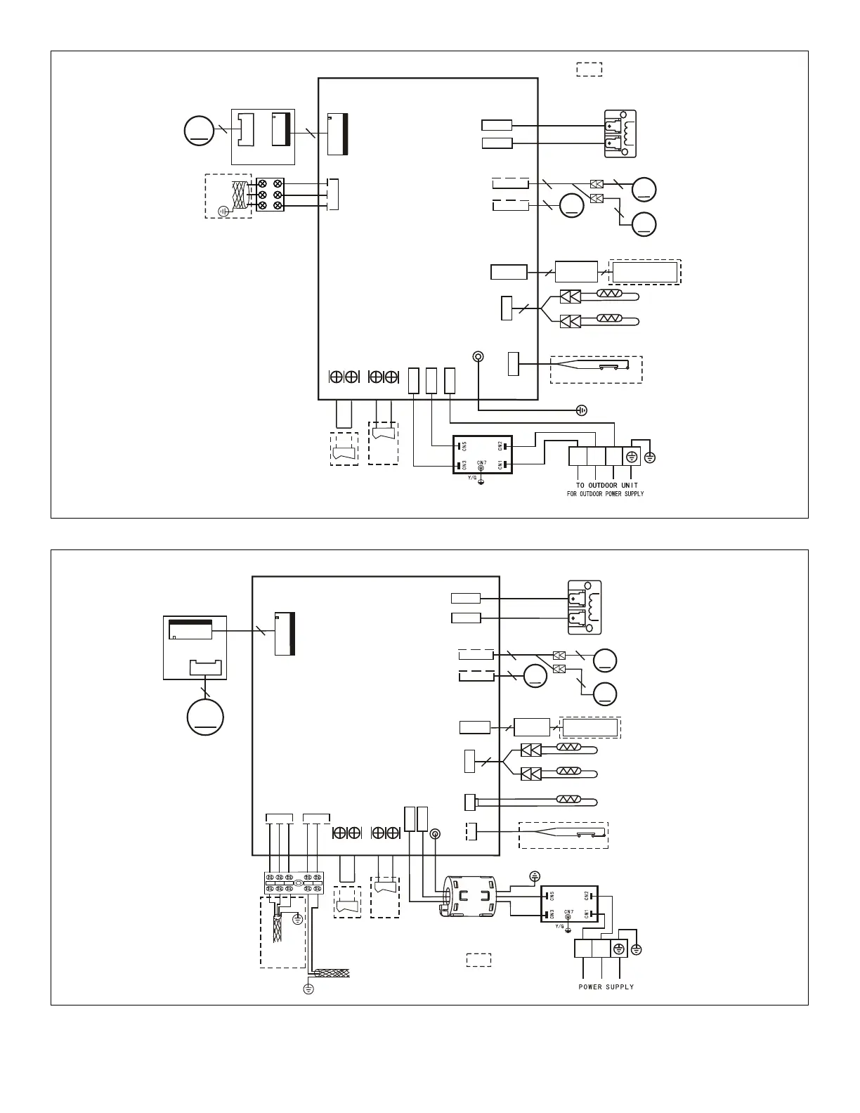
Figure 41. MCFA024S4-1P Unit Wiring Diagram
CN5
Reactor
CN8
CN18
CN7
T2B
OUTER PIPE TEMP. SENSOR
T2
T1
CN6
4
BLACK
WHITE
RED
RED
VSWING(INACTIVE)
CN21
CN24
M
M
M
5
5
5
5
SWING
INDOOR UNIT MAINBOARD
DC MOTOR
DRIVER MODULE
CN13
CN3
M
3
CN15
5
FAN1
Ceiling-Floor Type
CN23
ON/OFF
CN33
ALA RM
Alarm
Output
Remote
Control
CN19 CN16
BLUE
BLACK
YELLOW
GRAY
To CCM
Comm.Bus
To outdoor
Comm.Bus
WHITE
S1
S2
X Y
(
E
)
Y/G
CN3
CN2
CN1
BLACK
RED
Ferrite bead
FILTER-BOARD
L1
L2
RED
BLACK
Y/G
Y/G
Y/G
• • • • •
This symbol indicates the element is
optional,the actual shape shall prevail.
INDOOR COIL TEMP. SENSOR
ROOM TEMP. SENSOR
FAN
WATER LEVEL SWITCH
DISPLAY
BOAR D
10
CN10A
TO WIRE
CONTROLLE R
5
V1.0
2015/5/08
Figure 42. MCFA036S4-1P Unit Wiring Diagram

 Loading...