Lennox Mini-Split Service Manual / Page 103
DC MOTOR
DRIVER MODULE
CN13
CN3
3
CN15
5
M
CN6
T2
T1
4
BLACK
WHITE
INDOOR UNIT MAINBOARD
CN3
RED
CN2
CN1
Y/G
BLACK
CN41
YELLOW
CN5
WATER LEVEL SWITCH
Reactor
CN8
CN18
RED
RED
•••••
This symbol indicates the element is
optional,the actual shape shall prevail.
CN19
BLUE
BLACK
To CCM
Comm.Bus
WHITE
X Y
E
Y/G
1
23
FILTER-BOARD
BLACK
RED
CN23
ON/OFF
CN33
ALARM
Alarm
Output
Remote
Control
Ceiling-Floor Type
CN21
CN24
M
M
M
5
5
5
5
SWING
INDOOR COIL TEMP. SENSOR
ROOM TEMP. SENSOR
VSWING(INACTIVE)
FAN
DISPLAY
BOARD
10
CN10A
TO WIRE
CONTROLLER
5
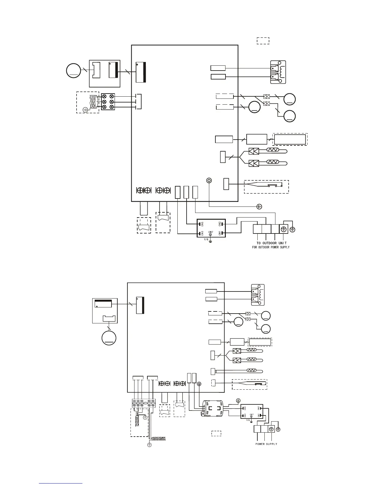
MCFA024S4-1P Unit Wiring Diagram
Typical wiring diagram.
Refer to wiring diagram on
the unit for actual wiring.
MCFA036S4-1P Unit Wiring Diagram
Typical wiring
diagram. Refer to
wiring diagram on the
unit for actual wiring.
CN5
Reactor
CN8
CN18
CN7
T2B
OUTER PIPE TEMP. SENSOR
T2
T1
CN6
4
BLACK
WHITE
RED
RED
VSWING(INACTIVE)
CN21
CN24
M
M
M
5
5
5
5
SWING
INDOOR UNIT MAINBOARD
DC MOTOR
DRIVER MODULE
CN13
CN3
M
3
CN15
5
FAN1
Ceiling-Floor Type
CN23
ON/OFF
CN33
ALARM
Alarm
Output
Remote
Control
CN19 CN16
BLUE
BLACK
YELLOW
GRAY
To CCM
Comm.Bus
To outdoor
Comm.Bus
WHITE
S1
S2
XY
(
E
)
Y/G
CN3
CN2
CN1
BLACK
RED
Ferrite bead
FILTER-BOARD
L1
L2
RED
BLACK
Y/G
Y/G
Y/G
•••••
This symbol indicates the element is
optional,the actual shape shall prevail.
INDOOR COIL TEMP. SENSOR
ROOM TEMP. SENSOR
FAN
WATER LEVEL SWITCH
DISPLAY
BOARD
10
CN10A
TO WIRE
CONTROLLER
5
V1.0
2015/5/08
 Loading...