4
NOTE: DIAGRAMS & ILLUSTRATIONS ARE NOT TO SCALE.
LENNOX HEARTH PRODUCTS • MERIT PLUS
®
DIRECT VENT GAS FIREPLACES (MPD33/35/40/45) • INSTALLATION INSTRUCTIONS
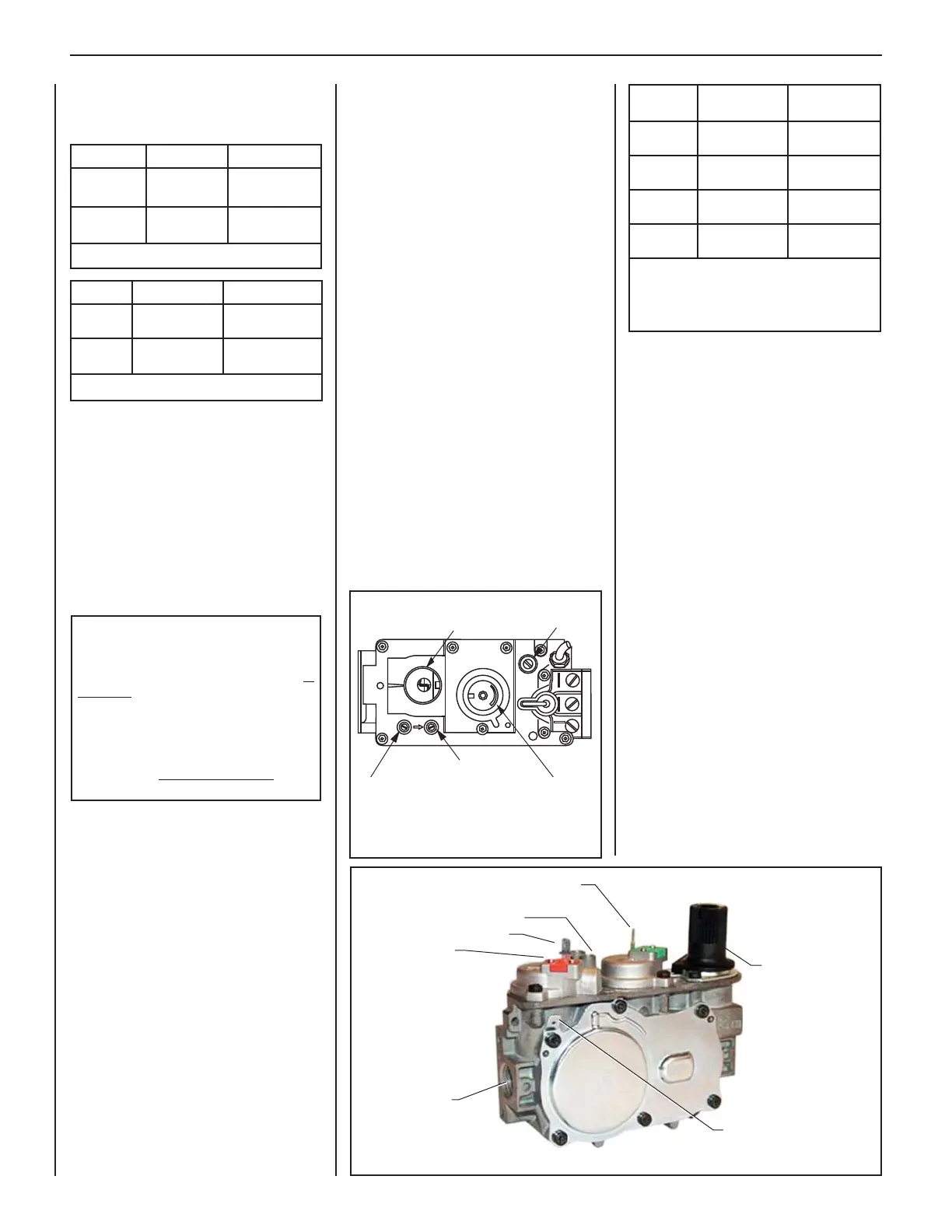
Test gauge connections are provided on
the front of the millivolt and electronic gas
control valve (identifi ed IN for the inlet and
OUT for the manifold side). The control
valves have a 3/8 in. (10 mm) NPT thread
inlet and outlet side of the valve (refer to
Figures 1 and 2).
Propane tanks are at pressures that will
cause damage to valve components. Verify
that the tanks have step down regulators to
reduce the pressure to safe levels.
Orifi ce Sizes—Sea Level to High Altitude
(All Models)
These appliances are tested and approved
for installation at elevations of 0–4500 ft
(0–1372 m) above sea level using the
standard burner orifi ce sizes (marked with an
"*" in Table 4). For elevations above 4500 ft,
contact your gas supplier or qualifi ed service
technician.
Deration—At higher elevations, the amount
of BTU fuel value delivered must be reduced
by either:
• Using gas that has been derated by the gas
company.
• Changing the burner orifi ce to a smaller
size as regulated by the local authorities
having jurisdiction and by the (USA)
National Fuel Gas Code NFPA 54—latest
edition / ANSI Z223.1-2009 or, in Canada,
the CAN/CSA-B149.1 codes—latest
edition.
Fuel # Low High
Natural
Gas
1.6 in. WC
(0.40 kPa)
3.5 in. WC
(0.87 kPa)
Propane
6.3 in. WC
(1.57 kPa)
10.0 in. WC
(2.49 kPa)
Table 3: Manifold Gas Supply Pressure
The appliance and its appliance main gas
valve must be disconnected from the gas
supply piping system during any pressure
testing of that system at test pressures in
excess of 1/2 psi (3.5 kPa).
The appliance must be isolated from the
gas supply piping system by closing its
equipment shutoff valve during any pressure
testing of the gas supply piping system at
test pressures equal to or less than 1/2 psi
(3.5 kPa).
Install the appliance according to the
regulations of the local authorities having
jurisdiction and, in the USA, the National
Fuel Gas Code NFPA 54—latest edition /
ANSI Z223.1-2009 or, in Canada, the CAN/
CSA-B149.1—latest edition.
Flame breadth, height and width will diminish
4% for every 1,000 feet of altitude. Gas Valve
Diagrams
. See Figure 1 for Millivolt models
and Figure 2 For Electronic Models.
In Canada - CAN/CGA-2.17-M91 (R2009)
(high altitude): THE CONVERSION SHALL
BE CARRIED OUT BY A MANUFACTURER’S
AUTHORIZED REPRESENTATIVE, IN
ACCORDANCE WITH THE REQUIREMENTS
OF THE MANUFACTURER, PROVINCIAL
OR TERRITORIAL AUTHORITIES HAVING
JURISDICTION AND IN ACCORDANCE
WITH THE REQUIREMENTS OF THE
CAN/CGA-B149.1 OR CAN/CGA-B149.2
INSTALLATION CODES.
REQUIREMENTS FOR THE
COMMONWEALTH OF MASSACHUSETTS
These fi replaces are approved for installation
in the US state of Massachusetts if the
following additional requirements are met:
• Install this appliance in accordance with
Massachusetts Rules and Regulations
248 C.M.R.
• Installation and repair must be done by
a plumber or gas fi tter licensed in the
Commonwealth of Massachusetts.
• The fl exible gas line connector used shall
not exceed 36 in. (92 cm) in length.
• The individual manual shut-off must be a
T-handle type valve.
Massachusetts Horizontal Vent Requirements
in the Commonwealth of Massachusetts,
horizontal terminations installed less than
seven (7) feet above the fi nished grade
must comply with the following additional
requirements:
• A hard wired carbon monoxide detector
with an alarm and battery back-up must
be installed on the fl oor level where the
gas fi replace is installed. The carbon
monoxide detector must comply with
NFPA 720, be ANSI/UL 2034 listed and be
ISA certifi ed.
• A metal or plastic identifi cation plate must
be permanently mounted to the exterior
of the building at a minimum height of
eight (8) feet above grade and be directly
in line with the horizontal termination.
The sign must read, in print size no less
than one-half (1/2) inch in size, GAS VENT
DIRECTLY BELOW. KEEP CLEAR OF ALL
OBSTRUCTIONS.
Fuel # Minimum Maximum
Natural
Gas
4.5 in. WC
(1.12 kPa)
10.5 in. WC
(2.61 kPa)
Propane
11.0 in. WC
(2.74 kPa)
13.0 in. WC
(3.23 kPa)
Table 2: Inlet Gas Supply Pressure
Gas Pressure—All Models
Tables 2 and 3 show the appliances' inlet and
manifold gas pressure requirements:
H
I
L
O
W
H
TPT
HT
P
T
P
I
L
O
T
P
I
L
O
T
O
N
O
F
F
IN
OUT
HI/LO Variable
Flame Height
Adjustment
Figure 1: SIT Millivolt Gas Valve
Manifold Pressure Tap
Inlet Pressure Tap
Pilot Adjustment
Screw
Main Gas Control Knob
OFF/PILOT/ON
Model
Series
Nat.Gas
drill size (inches)
Propane
drill size (inches)
MPD33
#47 (0.0785 in.)*
99K74•
0.048 in.
99K78•
MPD35
#44 (0.086 in.)*
60J80•
#55 (0.052 in.)*
19L52•
MPD40
#38 (0.102 in.)*
99K76•
0.062 in.
21L01•
MPD45
#37 (0.104 in.)*
24M10•
#52 (0.0635 in.)*
37G00•
Table 4: Burner Orifi ce Sizes
Elevation 0–4500 ft ( 0–1372 m)
* Standard size installed at factory
• Part /Cat. Number
Orange Wire
(from DFC Wire
Harness)
Main Gas Inlet
3/8 in. NPT
Green Wire
(from DFC Wire Harness)
Inlet (IN) Test Port
Manifold (OUT) Test Port
Figure 2: SIT Electronic Gas Valve
Hi/Lo Flame
Control Knob
Yellow Ground Wire
(from DFC Wire Harness)
 Loading...