Page 22
D−Extended Period Shutdown
Turn off thermostat or set to UNOCCUPIED" mode.
Close all shutoff valves in the oil supply line to guarantee no
oil leaks into burner. Turn off all power to unit. All access
panels, covers and vent caps must be in place and se
cured.
IV−HEATING SYSTEM SERVICE CHECKS
A−Oil Piping
All oil supply piping (factory and field) must be carefully
checked for oil leaks.
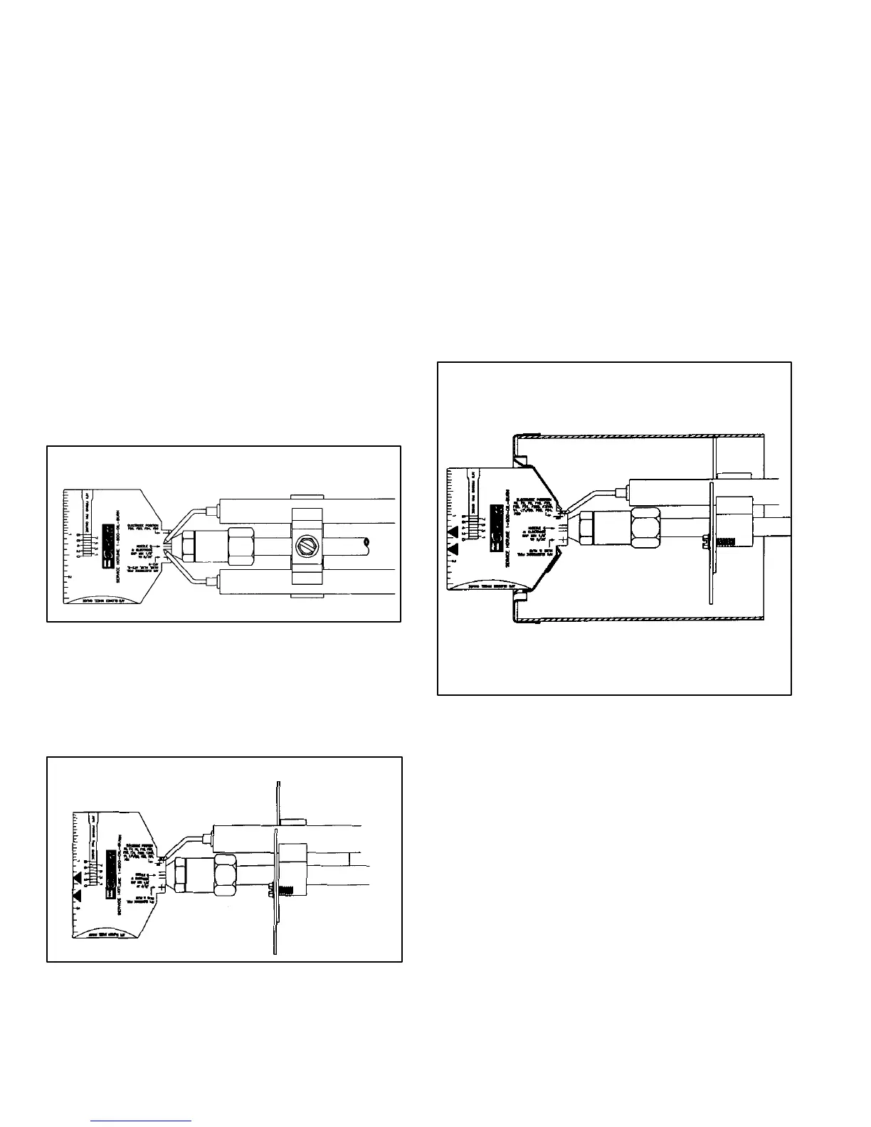
B−Electrode Adjustment
When adjusting the electrode, use the AFII multipurpose
gauge (Beckett part # T−500) packaged with each oil fur
nace, also available from Beckett.
To set the electrode tip gap spacing, position the gauge as
shown in figure 25. Align the center mark with the nozzle
and adjust the electrodes to the two outer marks (1/8"
[3mm] to 1/16" [2mm] minimum).
FIGURE 25
AFII ELECTRODE TIP
GAP
To position the electrode tips beyond the face of the nozzle
and above the center line, position the gauge as shown in
figure 26. Align the center mark with the nozzle and adjust
the electrodes to the AC cross marks.
FIGURE 26
AFII ELECTRODE POSITIONING
To check that the nozzle is approximately centered with
the head inside diameter, align the center mark of the
gauge with the center of the nozzle orifice, as shown in
figure 27, and move the gauge from side to side at sev
eral points. Be careful not to scratch the nozzle sur
face.
The Z" or zero dimension is important because it locates the
nozzle for the precise relationship with the combustion head.
To set the Z" dimension, position the gauge as shown in fig
ure 27 and loosen the nozzle line electrode assembly so that
it can be moved forward or backward in the air tube until the
nozzle becomes flush against the gauge. Tighten the nozzle
line escutcheon plate screw (shown in figure 9) to lock this
Z" dimension securely.
FIGURE 27
AFII NOZZLE CENTERING
C−Pressure Check
On −1 through −4 units use either the gauge port or
nozzle port to check operating pressure. On −5 units use
the nozzle port (−5 unit pumps are not equipped with
gauge port). The pump is factory set at 100 psig (689.5
kPa) for the O23Q2−70 and 140 psig (965.3 kPa) for all
other O23, OHR23, and OF23 units but is adjustable (see fig
ure 28). Never operate the pump in excess of 10 psig (69
kPa) above set point. Average nozzle cutoff pressure is
80 psig (551.6 kPa). To check the cutoff pressure install
a pressure gauge in nozzle port. For −5 units use the
same gauge used for operating pressure. Run the burn
 Loading...