Page 24
Table 7. HFC−410A Temp. (°F) − Pressure (Psig)
°F °C Psig °F °C Psig
−40 −40.0 11.6 60 15.6 170
−35 −37.2 14.9 65 18.3 185
−30 −34.4 18.5 70 21.1 201
−25 −31.7 22.5 75 23.9 217
−20 −28.9 26.9 80 26.7 235
−15 −26.1 31.7 85 29.4 254
−10 −23.3 36.8 90 32.2 274
−5 −20.6 42.5 95 35.0 295
0 −17.8 48.6 100 37.8 317
5 −15.0 55.2 105 40.6 340
10 −12.2 62.3 110 43.3 365
15 −9.4 70.0 115 46.1 391
20 −6.7 78.3 120 48.9 418
25 −3.9 87.3
125 51.7 446
30 −1.1 96.8 130 54.4 476
35 1.7 107 135 57.2 507
40 4.4 118 140 60.0 539
45 7.2 130
145 62.8 573
50 10.0 142
150 65.6 608
55 12.8 155
System Operation21
The outdoor unit and indoor blower cycle on demand from
the room thermostat. If the thermostat blower switch is in
the ON position, the indoor blower operates continuously.
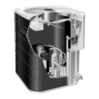
Filter Drier
The unit is equipped with a large−capacity biflow filter drier
which keeps the system clean and dry. If replacement is
necessary, order another of the same design and capacity.
The replacement filter drier must be suitable for use with
HFC−410A refrigerant.
Low Pressure Switch
The is equipped with an auto−reset low pressure switch
which is located on the vapor line. The switch shuts off the
compressor when the vapor pressure falls below the
factory setting. This switch, which is ignored during defrost
operation, closes at pressures at or above 40 psig and
opens at 25 psig. It is not adjustable.
High Pressure Switch
The is equipped with a manual-reset high pressure switch
(single−pole, single−throw) which is located on the liquid
line. The switch shuts off the compressor when discharge
pressure rises above the factory setting. The switch is
normally closed and is permanently adjusted to trip (open)
at 590 + 10 psig (4412 + 69 kPa).
NOTE − A Schrader core is under the pressure switches.
Defrost System22
The defrost system includes a defrost thermostat and a
defrost control.
Defrost Thermostat
The defrost thermostat is located on the liquid line between
the check/expansion valve and the distributor. When the
defrost thermostat senses 42°F (5.5°C) or cooler, its
contacts close and send a signal to the defrost control
board to start the defrost timing. It also terminates defrost
when the liquid line warms up to 70°F (21°C).
Defrost Control
The defrost control board includes the combined functions
of a time/temperature defrost control, defrost relay, time
delay, diagnostic LEDs, and a terminal strip for field wiring
connections.
The control provides automatic switching from normal
heating operation to defrost mode and back. During
compressor cycle (defrost thermostat is closed, calling for
defrost), the control accumulates compressor run times at
30, 60, or 90 minute field adjustable intervals. If the defrost
thermostat is closed when the selected compressor run
time interval ends, the defrost relay is energized and
defrost begins.
 Loading...