Page 8
The counterclockwise orbiting scroll draws gas into the outer
crescent shaped gas pocket created by the two scrolls as
illustrated in Figure 3, detail A. The centrifugal action of the
orbiting scroll seals off the flanks of the scrolls as illustrate din
Figure 3, detail B. As the orbiting motion continues, the gas is
forced toward the center of the scroll and the gas pocket
becomes compressed as illustrated in Figure 3, detail C.
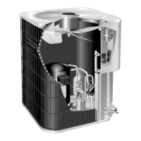
When the compressed gas reaches the center, it is
discharged vertically into a chamber and discharge port in the
top of the compressor as illustrate in Figure 5. The discharge
pressure forcing down on the top scroll helps seal off the
upper and lower edges (tips) of the scrolls as illustrated in
Figure 5. During a single orbit, several pockets of gas are
compressed simultaneously providing smooth continuous
compression.
The scroll compressor is tolerant to the effects of liquid
return. If liquid enters the scrolls, the orbiting scroll is allowed
to separate from the stationary scroll. The liquid is worked
toward the center of the scroll and is discharged. If the
compressor is replaced, conventional Lennox cleanup
practices must be used.
Due to its efficiency, the scroll compressor is capable of
drawing a much deeper vacuum than reciprocating
compressors. Deep vacuum operation can cause
internal fusite arcing resulting in damaged internal parts
and will result in compressor failure. Never use a scroll
compressor for evacuating or to pump system into a
vacuum. This type of damage can be detected and will
result in denial of warranty claims.
The scroll compressor is quieter than a reciprocating
compressor, however, the two compressors have much
different sound characteristics. The sounds made by a scroll
compressor do not affect system reliability, performance, or
indicate damage.
See compressor nameplate or ELECTRICAL DATA for
compressor specifications.
General Information7
These instructions are intended as a general guide and do
not supersede local codes in any way. Consult authorities
who have jurisdiction before installation.
Operating Gauge Set and Service Valves8
These instructions are intended as a general guide and do
not supersede local codes in any way. Consult authorities
who have jurisdiction before installation.
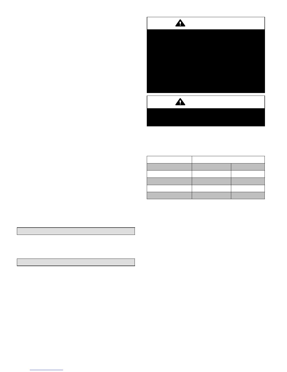
TORQUE REQUIREMENTS
When servicing or repairing heating, ventilating, and air
conditioning components, ensure the fasteners are
appropriately tightened. Table 1 lists torque values for
fasteners.
IMPORTANT
Only use Allen wrenches of sufficient hardness (50Rc −
Rockwell Harness Scale minimum). Fully insert the
wrench into the valve stem recess.
Service valve stems are factory−torqued (from 9 ft−lbs for
small valves, to 25 ft−lbs for large valves) to prevent
refrigerant loss during shipping and handling. Using an
Allen wrench rated at less than 50Rc risks rounding or
breaking off the wrench, or stripping the valve stem
recess.
See the Lennox Service and Application Notes #C−08−1
for further details and information.
IMPORTANT
To prevent stripping of the various caps used, the
appropriately sized wrench should be used and fitted
snugly over the cap before tightening.
When servicing or repairing HVAC components, ensure
the fasteners are appropriately tightened. Table 1 provides
torque values for fasteners.
Table 1. Torque Requirements
Parts Recommended Torque
Service valve cap 8 ft.− lb. 11 NM
Sheet metal screws 16 in.− lb. 2 NM
Machine screws #10 28 in.− lb. 3 NM
Compressor bolts 90 in.− lb. 10 NM
Gauge port seal cap 8 ft.− lb. 11 NM
USING MANIFOLD GAUGE SET
When checking the system charge, only use a manifold
gauge set that features low loss anti−blow back fittings.
Manifold gauge set used with HFC−410A refrigerant
systems must be capable of handling the higher system
operating pressures. The gauges should be rated for use
with pressures of 0 − 800 psig on the high side and a low
side of 30" vacuum to 250 psig with dampened speed to
500 psi. Gauge hoses must be rated for use at up to 800
psig of pressure with a 4000 psig burst rating.
OPERATING SERVICE VALVES
The liquid and vapor line service valves are used for
removing refrigerant, flushing, leak testing, evacuating,
checking charge and charging.
Each valve is equipped with a service port which has a
factory−installed valve stem. Figure 6 provides information
on how to access and operating both angle and ball service
valves.
 Loading...