Page 6
Unit Components
CONTROL BOX
TSA*S4 units are not equipped with a 24V transformer. All
24 VAC controls are powered by the indoor unit. Refer to
wiring diagram.
Electrical openings are provided under the control box
cover. Field thermostat wiring is made to color-coded
pigtail connections.
COMPRESSOR CONTACTOR K1
The compressor is energized by a contactor located in the
control box as illustated on Page 4. One or three−pole
contactors are used in this model. K1 is energized by the
indoor thermostat terminal Y1 (24V) when thermostat
demand is present.
CONDENSER FAN MOTOR B4 AND CAPACITOR C1
This model use a one−phase PSC fan motors which require a
run capacitor C1 located in the control box. Ratings for
C1 will be on fan motor nameplate. In all units, the
condenser fan is controlled by the compressor
contactor.
ELECTRICAL DATA tables in this manual show
specifications for condenser fans used in this model.
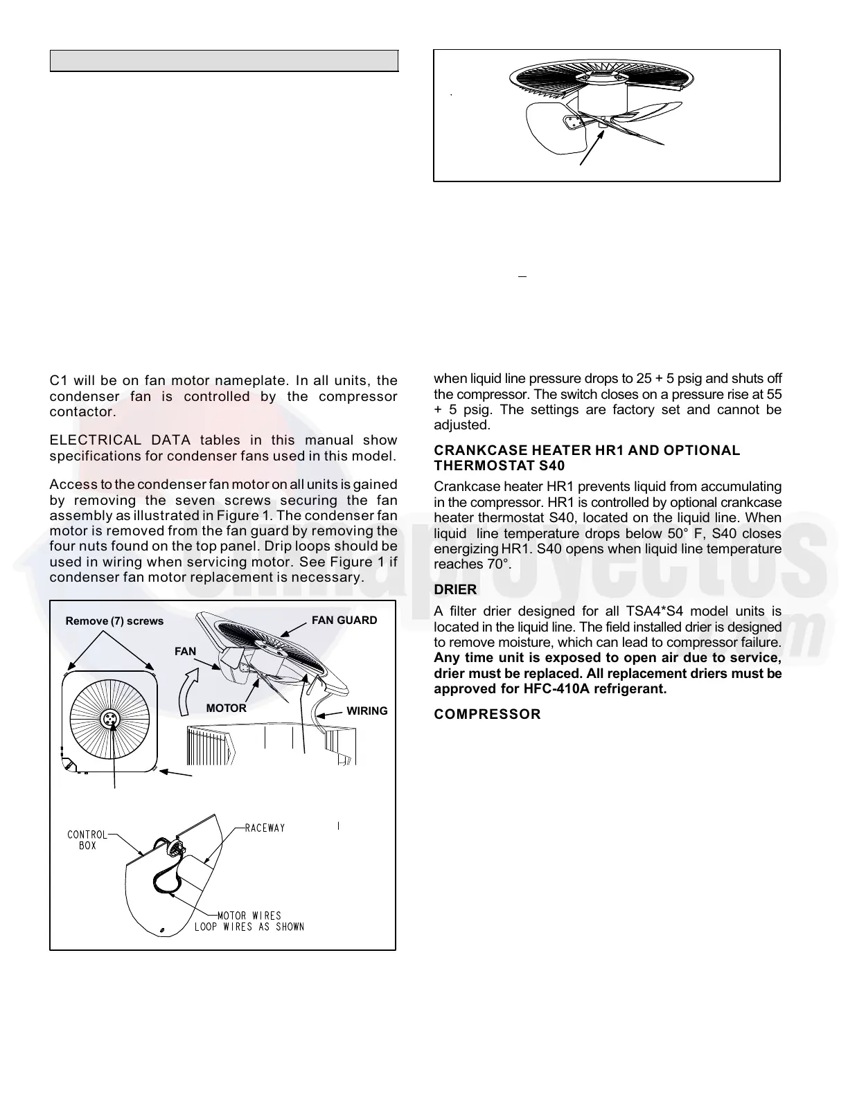
Access to the condenser fan motor on all units is gained
by removing the seven screws securing the fan
assembly as illustrated in Figure 1. The condenser fan
motor is removed from the fan guard by removing the
four nuts found on the top panel. Drip loops should be
used in wiring when servicing motor. See Figure 1 if
condenser fan motor replacement is necessary.
FAN
Remove (7) screws
REMOVE (7) SCREWS
SECURING FAN GUARD.
REMOVE FAN GUARD/FAN AS-
SEMBLY.
MOTOR
FAN GUARD
WIRING
RACEWAY
Remove (4) nuts
Figure 1. Condenser Fan Motor and Compressor
Access
ALIGN FAN HUB FLUSH WITH END OF SHAFT
Figure 2. Fan Hub Alignment.
HIGH PRESSURE SWITCH S4
The manual−reset high pressure switch is located in the
liquid line. When liquid line pressure exceeds the factory
setting of 590 + 10 psi, the switch opens and shuts off the
compressor.
LOSS OF CHARGE SWITCH S24 (FIELD
INSTALLED OPTION)
The loss of charge switch is N.C. auto re−set and located
on the liquid line of the compressor. The switch opens
when liquid line pressure drops to 25 + 5 psig and shuts off
the compressor. The switch closes on a pressure rise at 55
+ 5 psig. The settings are factory set and cannot be
adjusted.
CRANKCASE HEATER HR1 AND OPTIONAL
THERMOSTAT S40
Crankcase heater HR1 prevents liquid from accumulating
in the compressor. HR1 is controlled by optional crankcase
heater thermostat S40, located on the liquid line. When
liquid line temperature drops below 50° F, S40 closes
energizing HR1. S40 opens when liquid line temperature
reaches 70°.
DRIER
A filter drier designed for all TSA4*S4 model units is
located in the liquid line. The field installed drier is designed
to remove moisture, which can lead to compressor failure.
Any time unit is exposed to open air due to service,
drier must be replaced. All replacement driers must be
approved for HFC−410A refrigerant.
COMPRESSOR
All TSA*S4 units utilize a scroll compressor. The scroll
compressor design is simple, efficient and requires few
moving parts. A cutaway diagram of the scroll compressor is
illustrated in Figure 3. The scrolls are located in the top of the
compressor can and the motor is located just below. The oil
level is immediately below the motor.
The scroll is a simple compression concept centered around
the unique spiral shape of the scroll and its inherent
properties. Two identical scrolls are mated together forming
concentric spiral shapes as illustrated in Figure 4. One scroll
remains stationary, while the other is allowed to "orbit" (figure
5). Note that the orbiting scroll does not rotate or turn but
merely orbits the stationary scroll.
NOTE − During operation, the head of a scroll compressor
may be hot since it is in constant contact with discharge gas.
 Loading...