39
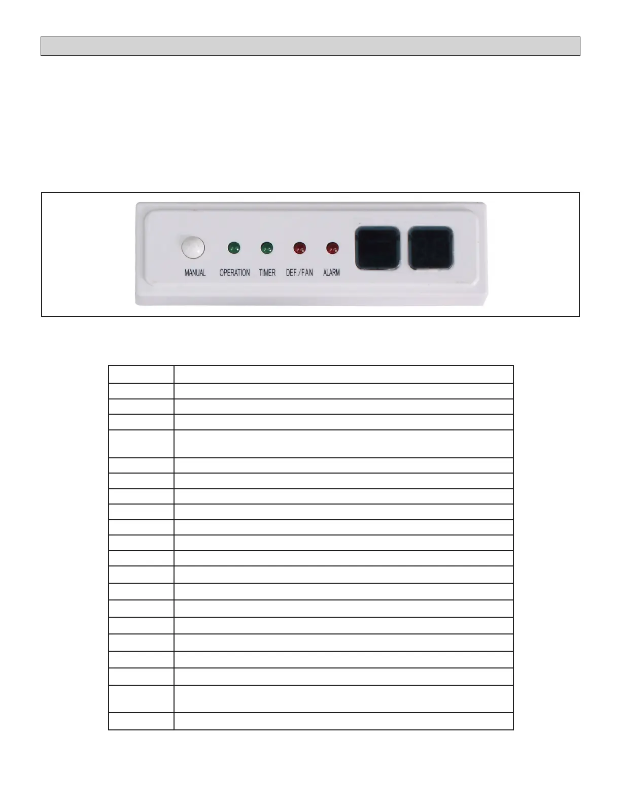
Digital Display
The AHU Control Kit is equipped with a receiver that has
a digital display that provides an error code. Refer to
Table 9 to view the error codes.
The error code will replace the temperature setting
displayed on the receiver. If more than one error has
occurred, the codes will alternate so that all codes are
shown.
Troubleshooting
Make note of the code (E1, EE, etc.), then reset the
display by pressing the ON/OFF button on the unit
controller. Press the ON/OFF button a second time
to reapply power to unit. If the code is still displayed,
disconnect and restore power at the unit disconnect
switch or circuit breaker. If the problem was temporary,
the code will not reappear. If the error code reappears
after power has been broken and restored at the
disconnect switch or circuit breaker, call VRF Technical
Support 1-844-438-8731.
Figure 32. Receiver/Display
Error Code Description
A0 Emergency stop
D8 Remote O
E0 Mode conict
E1
Communication error between Main AHU Control Kit and Sub AHU Con-
trol Kit(s)
H6 Communication error
E2 T1/T0 Temperature sensor malfunction
E3 T2 (Middle of evaporator sensor) malfunction
E4 T2B (Outlet of evaporator sensor) malfunction
E5 T2A (Inlet of evaporator sensor) malfunction
E6 Reserved
E7 EEPROM failure
E9 Communication error between controller and AHU Control Kit
Eb EXV malfunction
Ed Outdoor unit malfunction
EE High Water Alarm
F8 Mode Selection Box malfunction
FE No address the rst time power is ON
H8 Capacity setting, EXV Kit or Parallel total capacity incompatibility
H9
Fan control input has dry contact and 0~10V input at the same time or
ENC2, ENC3, and ENC4 are not set properly.
U4 MS self-inspection error
Table 9. Fault Code Display on Main AHU Control Kit
 Loading...