29
Heating Source Conguration and Control
Alternate and Auxiliary Heat Control Conguration
Identify if there is an alternate or auxiliary heat source
connected to the air handler using SW1 on the Main AHU
control kit.
Dry contact AUXH control logic is ALT. (default)
1
ON
SW1
1
ON
Dry contact AUXH control logic is AUX.
Main AHU Control Kit Only
Parallel Control Mode 1.
One coil connected to multiple AHU Con-
trol Kits. T1, T2, T2A, and T2B should be
connected with the Main kit.
Main AHU Control Kit Only
Parallel Control Mode 2.
One coil connected to one AHU Control Kit.
In the case of multiple coils in one AHU,
each coil is connected to one kit individu-
ally, T2, T2A, T2B are connected with the
corresponding kit, and T1 should connected
with the Main kit.
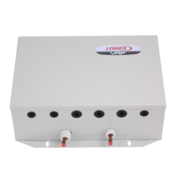
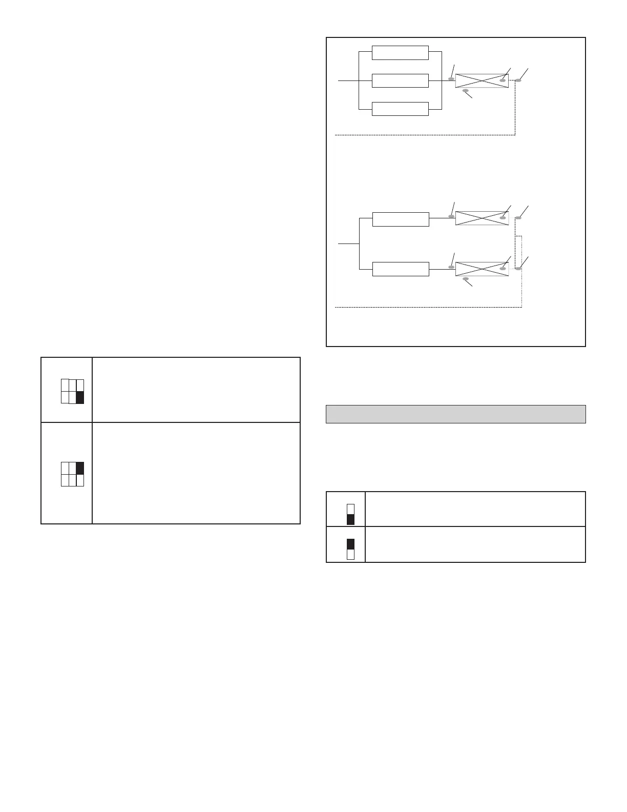
Parallel Control Setting
Identify if there is one AHU Control Kit controlling each coil
or if there are multiple parallel AHU Control Kits controlling
one coil using SW5-3.
There may be single or multiple coils in a large AHU over
8 ton (see Table 2). 2, 3 or 4 kits are wired in parallel as
main kit and sub kits. SW5-3 denes whether the parallel
kits connect to single coil or each kit of the parallel set
connects to a coil.
SW5-3 set at 0 (default) indicates 2, 3 or 4 kits are wired
in parallel to regulate the refrigerant ow to single coil.
Four (4) temperature sensors T1, T2, T2A and T2B from
the main kit are placed in the AHU. Four (4) temperature
sensors from each of the sub kits shall be disconnected.
Do not discard, save for future use as spare parts.
SW5-3 set at 1 indicates 2, 3 or 4 kits are wired in parallel.
Each regulates the refrigerant ow to a coil individually and
shares the return air sensor T1 from the main kit. Three (3)
temperature sensors T2, T2A and T2B from each kit are
placed in a coil respectively. T1 temp sensors from all the
sub kits shall be disconnected. Do not discard, save for
future use as spare parts.
Set the quantity of parallel kits and assign addresses to
each kit using SW2.
AHUK 3 (Sub)
AHUK 2 (Sub)
AHUK 1 (Main)
T2A
T2B
T2
T1
Mode 1
Coil
AHUK 2 (Sub)
AHUK 1 (Main)
Mode 2
T2A
T2B
T2
T1
Coil 2
T2A
T2B
T2
Coil 1
NOTE - T1, T2, T2A, and T2B should be connected with the Main kit.
NOTE - T2, T2A, T2B are connected with the corresponding kit, and
T1 should connected with the Main kit.
Figure 21. Parallel Control Setting
ON
1
2 3
SW5
ON
1
2 3
SW5
 Loading...