Page 8
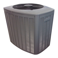
FIGURE 9
Remove
screws
Remove
screws
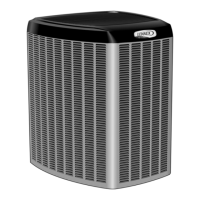
FIGURE 10
E − Discharge Line Thermostat (S5)
The discharge line thermostat is NC, auto re−set and located
on the discharge line of the compressor. The switch opens
when discharge line temperatures exceeds the factory set-
ting of 220° +
5° F and shuts down the compressor.
F − High Pressure Switch (S4)
XC14 units are equipped with a high pressure switch that is
located in the liquid line of the compressor. The switch
(SPST, manual reset, normally closed) removes power from
the compressor contactor control circuit when discharge
pressure rises above factory setting at 590 +
10 psi.
G − Crankcase Heater (HR1) &
Thermostat (S40) 4 and 5 ton only
XC14−048 and −060 units are equipped with a 70 watt belly
band type crankcase heater. HR1 prevents liquid from accu-
mulating in the compressor. HR1 is controlled by a thermo-
stat located on the liquid line. When liquid line temperature
drops below 50° F the thermostat closes energizing HR1.
The thermostat will open, de−energizing HR1 once liquid line
temperature reaches 70° F.
H − Loss of Charge Switch (option) (S24)
The loss of charge switch is NC, auto re−set and located on
the suction line of the compressor.The switch opens when
suction line pressure drops to 25psi +
5 (shutting down the
compressor) and will close when suction line pressure rises
to 55psi +
5.
III − REFRIGERANT SYSTEM
A − Plumbing
Field refrigerant piping consists of liquid and suction lines
from the condensing unit (sweat connections) to the indoor
evaporator coil (sweat connections). Use Lennox L15
(sweat) series line sets as shown in table 1.
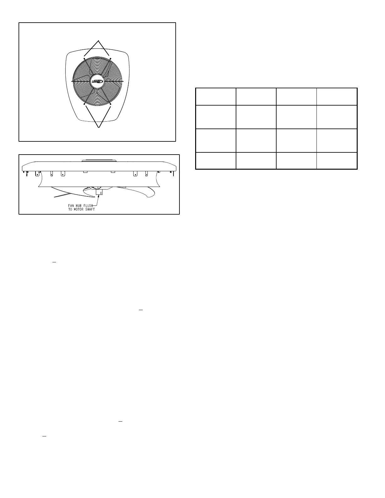
TABLE 1
Unit
Liquid
Line
Suction
Line
L15 Line
Sets
018, −024,
−030,
3/8 in.
(10 mm)
3/4 in.
(19 mm)
L15−41
20 ft. − 50 ft.
(6 m − 15 m)
−036, −042,
−048
3/8 in.
(10 mm)
7/8 in.
(22 mm)
L15−65
30 ft. − 50 ft.
(9 m − 15 m)
−060
3/8 in.
(10 mm)
1−1/8 in.
(29 mm)
Field
Fabricated
The liquid line and vapor line service valves (figures 11 and
12) and gauge ports are accessible from the outside of the
unit. Use the service ports for leak testing, evacuating,
charging and checking charge.
Each valve is equipped with a service port which has a facto-
ry−installed Schrader valve. A service port cap protects the
Schrader valve from contamination and serves as the pri-
mary leak seal. Service valves are not rebuildable. If a valve
has failed, you must replace it.
To Access Schrader Port:
1 − Remove service port cap with an adjustable wrench.
2 − Connect gauge to the service port.
3 − When testing is complete, replace service port cap. Tight-
en finger tight, then an additional 1/6 turn.
To Open Service Valve:
1 − Remove the stem cap with an adjustable wrench.
2 − Using the adjustable wrench to keep the valve station-
ary, use a service wrench with a hex−head extension to
back the stem out counterclockwise as far as it will go.
NOTE − Use a 3/16" hex head extension for 3/8" line
sizes or a 5/16" extension for large line sizes.
3 − Replace the stem cap. Tighten finger tight, then tighten
an additional 1/6 turn.
 Loading...