Page 6
B − Compressor (B1)
The scroll compressor used in all XC14 model units, is de-
signed for use with R410A refrigerant and operation at high
pressures. Compressors are shipped from the factory
charged with 3MA (32MMMA) P.O.E. oil. All XC14 compres-
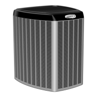
sors are equipped with a factory installed sound cover made
of polyethylene containing a 2 inch thick batt of fiberglass in-
sulation. See figure 5.
See ELECTRICAL DATA table at the front of this manual or
compressor nameplate for compressor specifications.
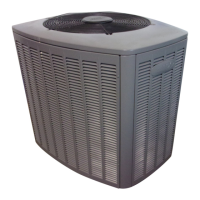
The scroll compressor design is simple, efficient and requires
few moving parts. A cutaway diagram of the scroll compressor
is shown in figure 4. The scrolls are located in the top of the
compressor can and the motor is located just below. The oil lev-
el is immediately below the motor.
FIGURE 4
SCROLL COMPRESSOR
DISCHARGE
SUCTION
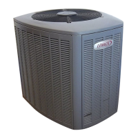
The scroll is a simple compression concept centered around
the unique spiral shape of the scroll and its inherent properties.
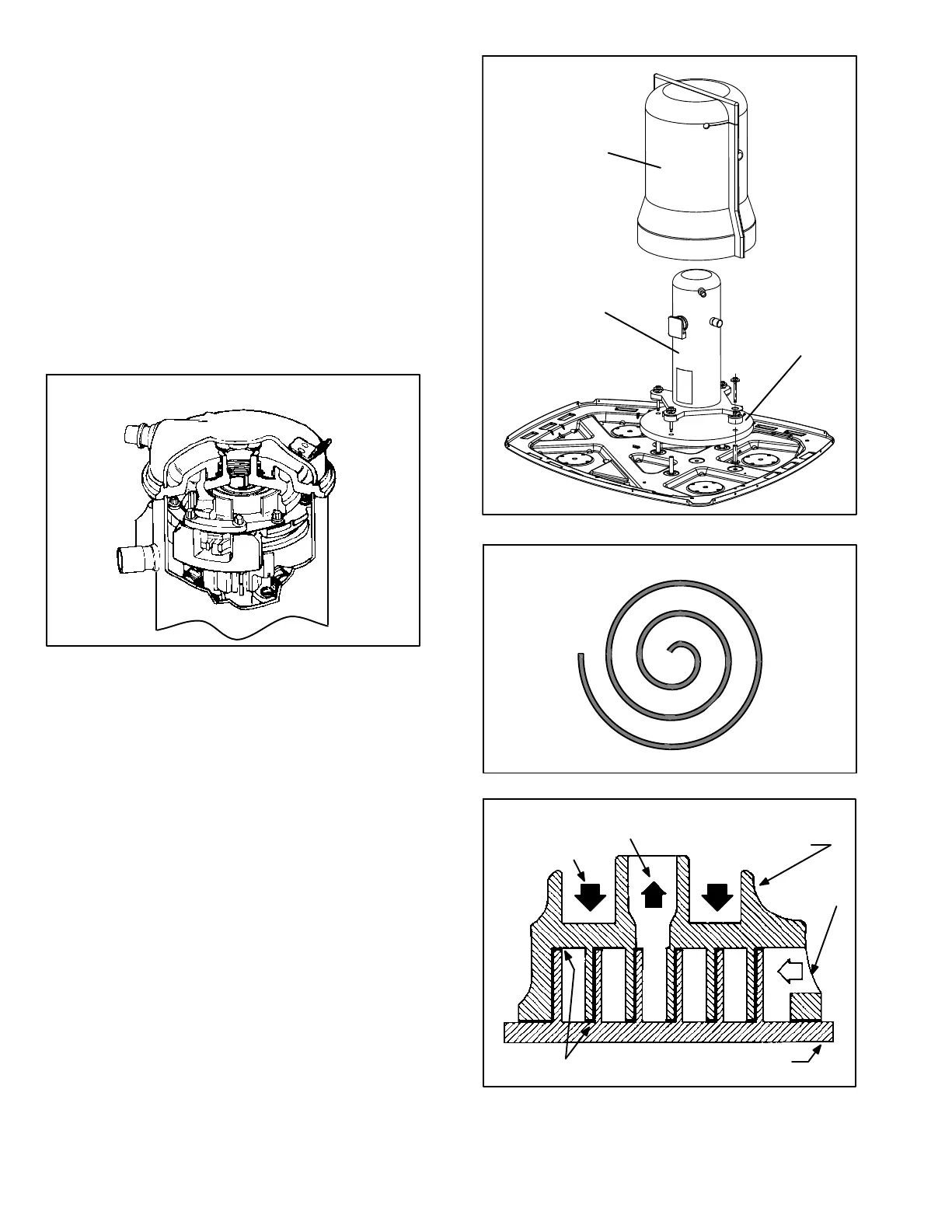
Figure 6 shows the basic scroll form. Two identical scrolls are
mated together forming concentric spiral shapes (figure 7). One
scroll remains stationary, while the other is allowed to "orbit" (fig-
ure 8). Note that the orbiting scroll does not rotate or turn but
merely orbits the stationary scroll.
NOTE − During operation, the head of a scroll compressor may
be hot since it is in constant contact with discharge gas.
FIGURE 5
SOUND COVER
COMPRESSOR
SOUND PAD
FIGURE 6
SCROLL FORM
FIGURE 7
STATIONARY SCROLL
ORBITING SCROLL
DISCHARGE
SUCTION
CROSS−SECTION OF SCROLLS
TIPS SEALED BY
DISCHARGE PRESSURE
DISCHARGE
PRESSURE
 Loading...