Page 17
XC15 SERIES
NOTE − ROOM THERMOSTATS WITH SERVICE OR
CHECK LIGHT FEATUREThe room thermostat may
blink the Check" or Service" LED or it may come on solid.
Confirm fault by observing and interpreting the code from
the LSOM yellow alert LED at the unit.
LSOMInstallation verification
To verify correct LSOM installation, two functional tests
can be performed. Disconnect power from the compressor
and force a thermostat call for cooling. The red trip LED
should turn on indicating a compressor trip as long as
24VAC is measured at the Y terminal. If the red LED does
not function as described, refer to table 8 to verify the wir-
ing. Disconnect power from the compressor and 24VAC
power from LSOM. Remove the wire from the Y terminal of
LSOM and reapply power to the compressor, allowing the
compressor to run. The yellow alert LED will begin flashing
a code 8 indicating a welded contactor. Disconnect power
from the compressor and 24VAC power from the LSOM.
While the LSOM is off, reattach the wire to the Y terminal.
Reapply power to the compressor and 24VAC power to the
LSOM; the yellow alert LED will flash the previous code 8
for one minute and then turn off. If the yellow LED does not
function as described, refer to table 8 to verify the wiring.
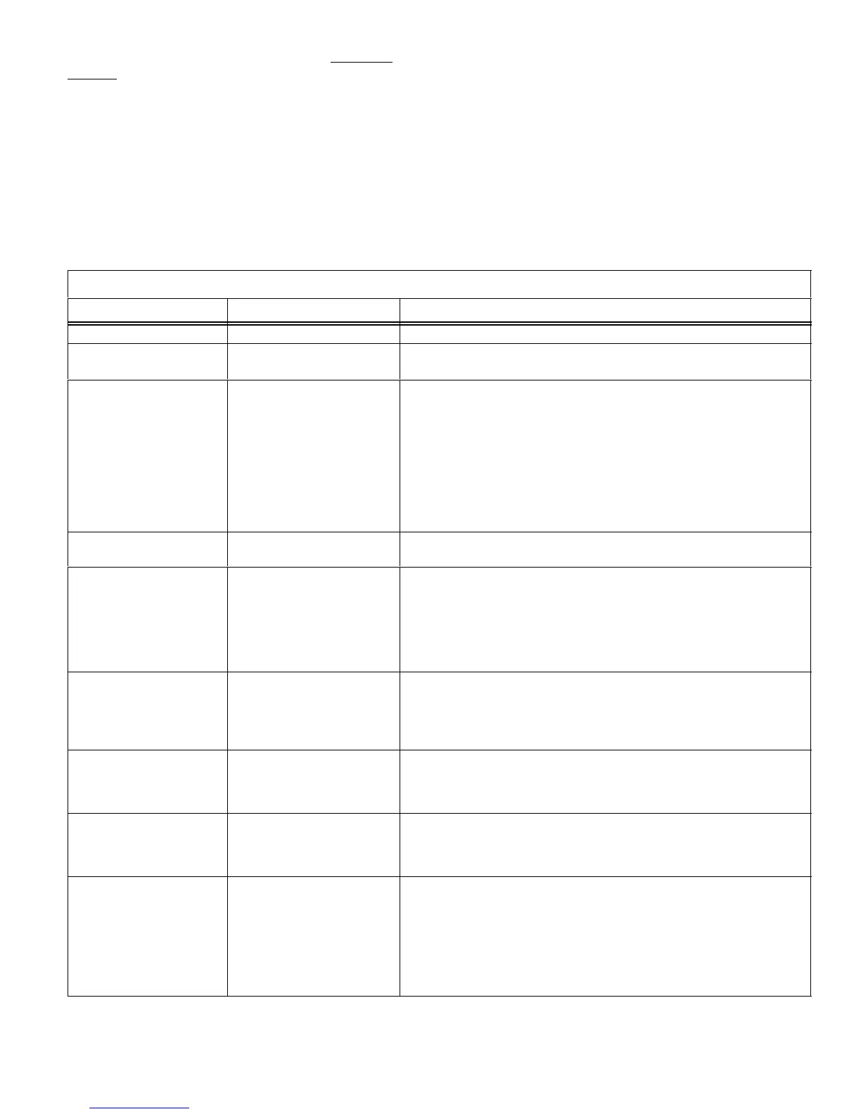
Table 8
System Operation Monitor LED Troubleshooting Codes
Status LED Condition Status LED Description Status LED Troubleshooting Information
Green Power" LED ON Module has power 24VAC control power is present at the module terminal.
Green Power" LED OFF Module not powering up Determine/verify that both R and C module terminals are connected
and voltage is present at both terminals.
Red Trip" LED ON System and compressor
check out OK
1
Verify Y terminal is connected to 24VAC at contactor coil.
2
Verify voltage at contactor coil falls below 0.5VAC when off.
3
Verify 24VAC is present across Y and C when thermostat demand
signal is present; if not present, R and C wires are reversed.
Thermostat demand signal
Y1 is present, but compres-
sor not running
1
Compressor protector is open.
2
Outdoor unit power disconnect is open.
3
Compressor circuit breaker or fuse(s) is open.
4
Broken wire or connector is not making contact.
5
Low pressure switch open if present in the system.
6
Compressor contactor has failed to close.
Red Trip" & Yellow
Alert" LEDs Flashing
Simultaneous flashing. Indicates that the control circuit voltage is too low for operation.
Yellow Alert" Flash
Code 1*
Long Run Time − Compres-
sor is running extremely
long run cycles
1
Low refrigerant charge.
2
Evaporator blower is not running.
3
Evaporator coil is frozen.
4
Faulty metering device.
5
Condenser coil is dirty
.
6
Liquid line restriction (filter drier blocked if present)
.
7
Thermostat is malfunctioning
.
Yellow Alert" Flash
Code 2*
System Pressure Trip −
Discharge or suction pres-
sure out of limits or
compressor overloaded
1
High head pressure.
2
Condenser coil poor air circulation (dirty, blocked, damaged).
3
Condenser fan is not running.
4
Return air duct has substantial leakage.
5
If low pressure switch is present, see Flash Code 1 information.
Yellow Alert" Flash
Code 3*
Short Cycling − Compres-
sor is running only briefly
1
Thermostat demand signal is intermittent.
2
Time delay relay or control board is defective.
3
If high pressure switch is present, see Flash Code 2 information.
4
If low pressure switch is present, see Flash Code 1 information.
Yellow Alert" Flash
Code 4*
Locked Rotor
1
Run capacitor has failed.
2
Low line voltage (contact utility if voltage at disconnect is low).
3
Excessive liquid refrigerant in the compressor.
4
Compressor bearings are seized.
Yellow Alert" Flash
Code 5*
Open Circuit
1
Outdoor unit power disconnect is open.
2
Unit circuit breaker or fuse(s) is open.
3
Unit contactor has failed to close.
4
High pressure switch is open and requires manual reset.
5
Open circuit in compressor supply wiring or connections.
6
Unusually long compressor protector reset time due to extreme ambi-
ent temperature.
7
Compressor windings are damaged.
table continued on next page
 Loading...