Page 16
505095M 1/3/06
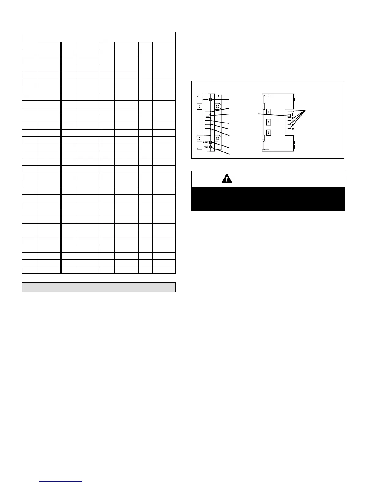
Table 7
R−410A Temperature (°F) − Pressure (Psig)
°F Psig °F Psig °F Psig °F Psig
32 100.8 63 178.5 94 290.8 125 445.9
33 102.9 64 181.6 95 295.1 126 451.8
34 105.0 65 184.3 96 299.4 127 457.6
35 107.1 66 187.7 97 303.8 128 463.5
36 109.2 67 190.9 98 308.2 129 469.5
37 111.4 68 194.1 99 312.7 130 475.6
38 113.6 69 197.3 100 317.2 131 481.6
39 115.8 70 200.6 101 321.8 132 487.8
40 118.0 71 203.9 102 326.4 133 494.0
41 120.3 72 207.2 103 331.0 134 500.2
42 122.6 73 210.6 104 335.7 135 506.5
43 125.0 74 214.0 105 340.5 136 512.9
44 127.3 75 217.4 106 345.3 137 519.3
45 129.7 76 220.9 107 350.1 138 525.8
46 132.2 77 224.4 108 355.0 139 532.4
47 134.6 78 228.0 109 360.0 140 539.0
48 137.1 79 231.6 110 365.0 141 545.6
49 139.6 80 235.3 111 370.0 142 552.3
50 142.2 81 239.0 112 375.1 143 559.1
51 144.8 82 242.7 113 380.2 144 565.9
52 147.4 83 246.5 114 385.4 145 572.8
53 150.1 84 250.3 115 390.7 146 579.8
54 152.8 85 254.1 116 396.0 147 586.8
55 155.5 86 258.0 117 401.3 148 593.8
56 158.2 87 262.0 118 406.7 149 601.0
57 161.0 88 266.0 119 412.2 150 608.1
58 163.9 89 270.0 120 417.7 151 615.4
59 166.7 90 274.1 121 423.2 152 622.7
60 169.6 91 278.2 122 428.8 153 630.1
61 172.6 92 282.3 123 434.5 154 637.5
62 175.4 93 286.5 124 440.2 155 645.0
System Operation
The outdoor unit and indoor blower cycle on demand from
the room thermostat. When the thermostat blower switch
is in the ON position, the indoor blower operates continu-
ously.
High Pressure Switch
XC15 units are equipped with a high pressure switch that is
located in the liquid line to the compressor. The switch is a
SPST, manual−reset switch that is normal closed. The
switch opens at 590 psi.
Low Pressure Switch
XC15 units are equipped with a low pressure switch that is
located in the vapor line to the compressor. The switch is a
SPST, auto−reset switch that is normal closed. The switch
opens at 40 psi and closes at 90 psi.
Filter Drier
A drier is factory−installed in each XC15 unit. A replace-
ment drier is available from Lennox. Refer to Lennox Re-
pair Part Program.
System Operation Monitor (LSOM)
The diagnostic indicator detects the most common fault
conditions in the air conditioning system. When an abnor-
mal condition is detected, the module communicates the
specific condition through its ALERT and TRIP lights. The
module is capable of detecting both mechanical and elec-
trical system problems. See figure 18 for the system op-
eration monitor.
System Operation Monitor
Figure 18
.25" SPADE
CONNECTOR (4)
POWER LED
Y
DATA OUTPUT
CONNECTOR
L
R
C
ALERT LED
TRIP LED
IMPORTANT
This monitor does not provide safety protection.
The monitor is a monitoring device only and cannot
control or shut down other devices.
LSOMLED Functions
Power LED (green)indicates voltage within the range of
19−28VAC is present at the system monitor power connec-
tion.
Alert LED (yellow)communicates an abnormal system
condition through a unique Flash Code the alert LED
flashes a number of times consecutively; then pauses;
then repeats the process. This consecutive flashing corre-
lates to a particular abnormal condition.
Trip LED (red)indicates there is a demand signal from
the thermostat but no current to the compressor is de-
tected by the module.
Refer to table 8 for the complete explanation of trouble-
shooting codes.
Resetting alert codesAlert codes can be reset manual-
ly or automatically:
S Manual reset: Cycle the 24VAC power to LSOM off
and on. After power up, existing code will display for
1 minute and then clear.
S Automatic reset: After an alert is detected, the LSOM
continues to monitor the compressor and system.
When/if conditions return to normal, the alert code is
turned off automatically.
LSOML terminal connection
The L connection is used to communicate alert codes to
the room thermostat. On selected Lennox SignatureStatt
thermostats, a blinking check" LED will display on the
room thermostat and on select White-Rodgers room ther-
mostats, an icon on the display will flash. Either will flash at
the same rate as the LSOM yellow alert LED.
 Loading...