Page 18
505095M 1/3/06
System Operation Monitor LED Troubleshooting Codes
Status LED Condition Status LED Troubleshooting InformationStatus LED Description
Yellow Alert" Flash
Code 6*
Open Start Circuit − Current
only in run circuit
1
Run capacitor has failed.
2
Open circuit in compressor start wiring or connections.
3
Compressor start winding is damaged.
Yellow Alert" Flash
Code 7*
Open Run Circuit − Current
only in start circuit
1
Open circuit in compressor start wiring or connections.
2
Compressor start winding is damaged.
Yellow Alert" Flash
Code 8*
Welded Contactor − Com-
pressor always runs
1
Compressor contactor failed to open.
2
Thermostat demand signal not connected to module.
Yellow Alert" Flash
Code 9*
Low Voltage − Control cir-
cuit <17VAC
1
Control circuit transformer is overloaded.
2
Low line voltage (contact utility if voltage at disconnect is low).
*Flash code number corresponds to a number of LED flashes, followed by a pause, and then repeated. Reset ALERT flash
code by removing 24VAC power from monitor; last code will display for 1 minute after monitor is powered on.
Last code will display for 1 minute when power is cycled to module. Power must be on to module for a minimum of 1 minute
for code to clear.
Maintenance
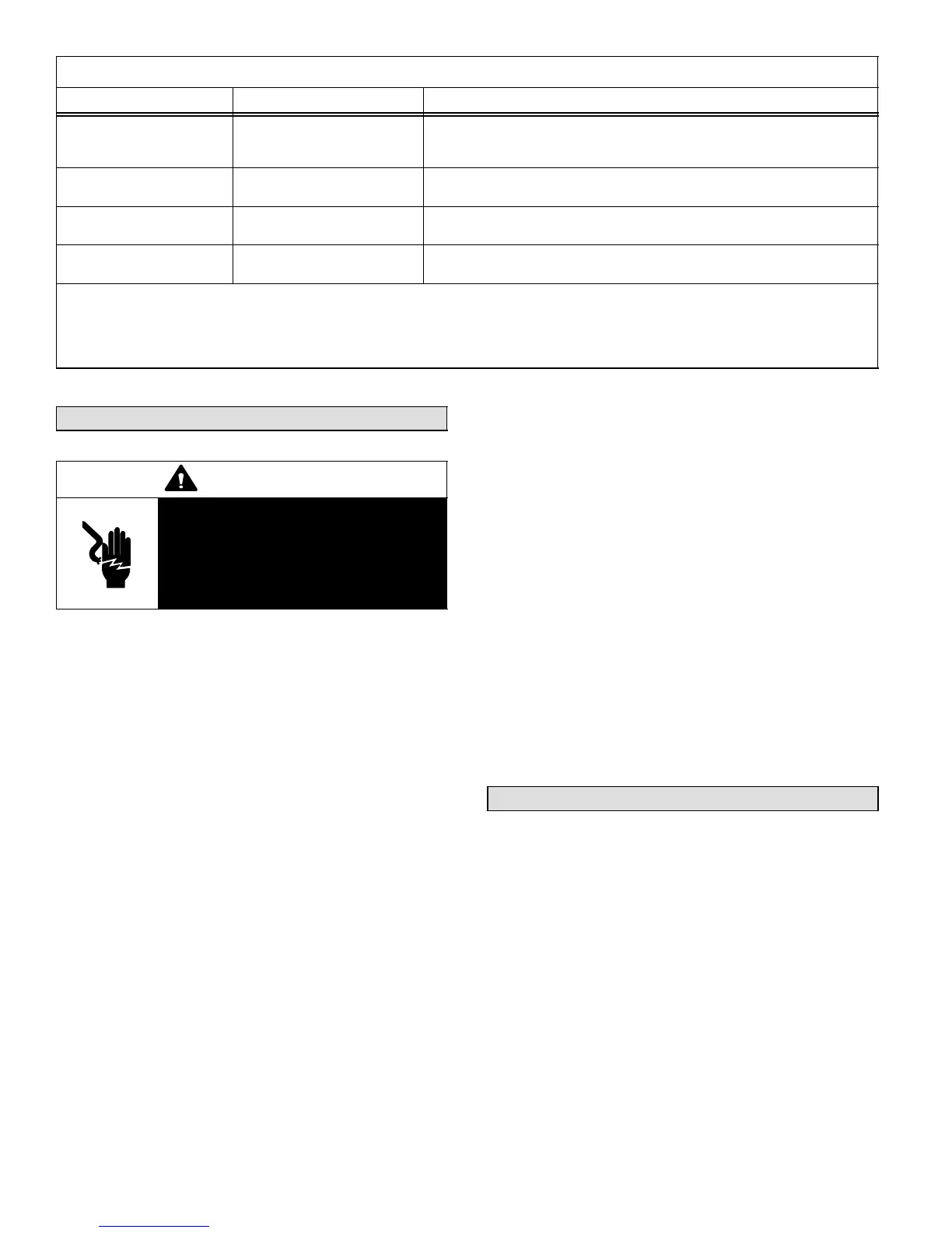
WARNING
Electric shock hazard. Can cause inju-
ry or death. Before attempting to per-
form any service or maintenance, turn
the electrical power to unit OFF at dis-
connect switch(es). Unit may have
multiple power supplies.
Maintenance and service must be performed by a qualified
installer or service agency. At the beginning of each cool-
ing season, check the system as follows:
NOTE − Outdoor fan motor is prelubricated and sealed. No
further lubrication is needed.
1. Clean and inspect the outdoor coil. The coil may be
flushed with a water hose. Ensure the power is turned
off before you clean the coil.
2. Check connecting lines and coils for signs of oil leaks.
3. Check wiring for loose connections.
4. Check for correct voltage at unit (unit operating).
5. Check amp−draw outdoor fan motor.
Unit nameplate _________ Actual ____________ .
NOTE − If owner reports insufficient cooling, the unit
should be gauged and refrigerant charge checked.
Refer to section on refrigerant charging section
(Page 13).
Indoor Coil
1. Clean coil, if necessary.
2. Check connecting lines and coils for signs of oil leaks.
3. Check condensate line and clean, if necessary.
Indoor Unit
1. Clean or change filters.
2. Adjust blower speed for cooling. Measure the pressure
drop over the coil to determine the correct blower CFM.
Refer to the unit information service manual for pressure
drop tables and procedure.
3. Check blower for accumulation of dirt or debris.
4. Check all wiring for loose connections
5. Check for correct voltage at unit (blower operating).
6. Check amp−draw on blower motor
Unit nameplate_________ Actual ____________.
Optional Accessories
Optional accessories for the XC15 include the following
(also, see Engineering Handbook for more details):
S Timed-off control
S Low ambient kit
 Loading...