Page 15
XC21
ATTACH THE MANIFOLD GAUGE SET FOR BRAZING
LIQUID AND SUCTION LINE SERVICE VALVES
OUTDOOR
UNIT
LIQUID LINE
SUCTION LINE
LIQUID LINE SERVICE
VALVE
SUCTION LINE
SERVICE VALVE
ATTACH
GAUGES
INDOOR
UNIT
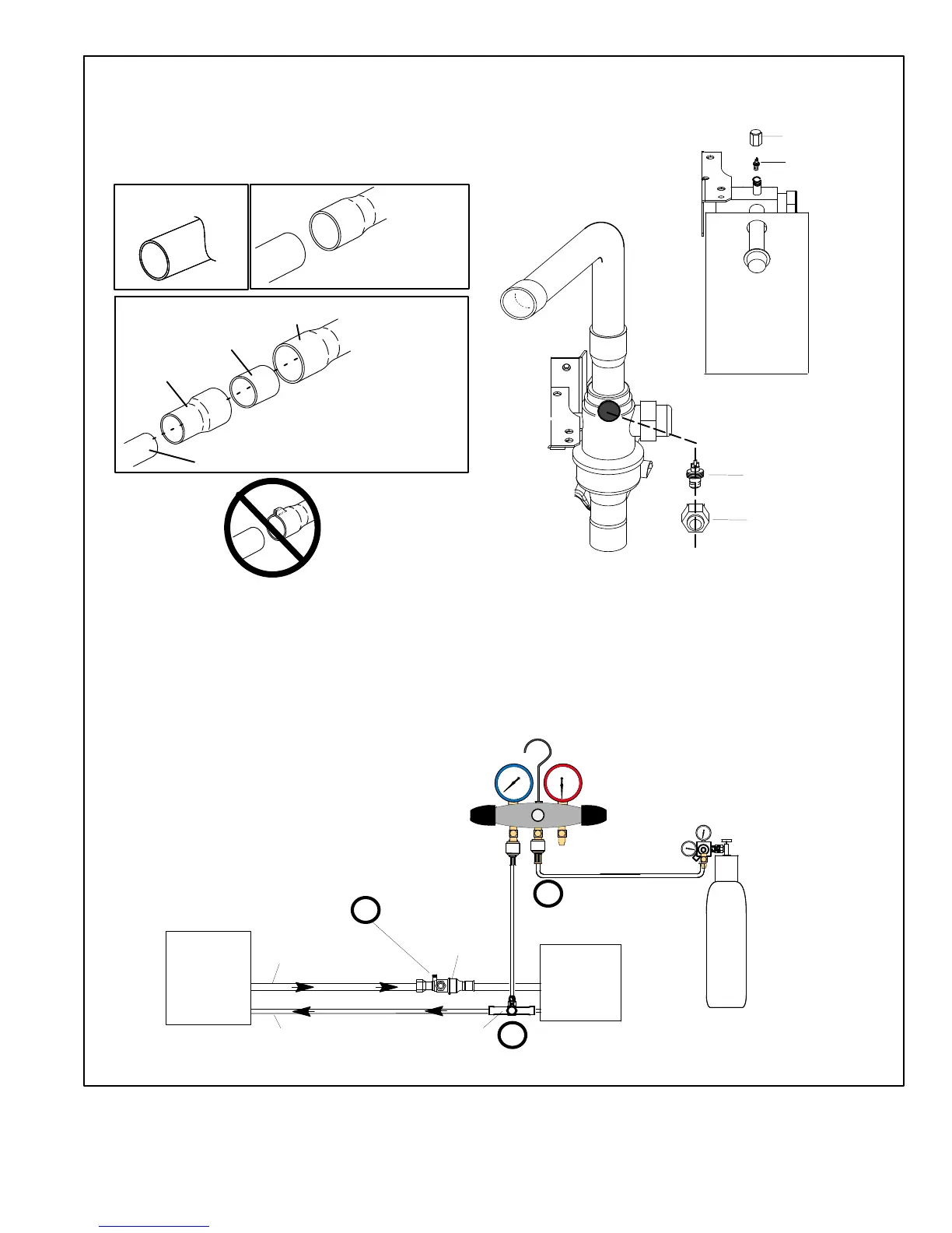
SUCTION SERVICE PORT MUST BE OPEN AND
SERVICE PORT CORE REMOVED TO ALLOW
EXIT POINT FOR NITROGEN FLOW
A Connect gauge set low pressure side to liquid line
service valve (service port).
B Connect gauge set center port to bottle of nitrogen
with regulator.
C With valve core removed from the suction line service
port, nitrogen flow will have an exit point.
NITROGEN
HIGH
LOW
B
A
C
PIPING PANEL REMOVAL AND PREPARING LINE
SET
CAP AND CORE REMOVAL
Remove piping panel for easier access to service valves. Cut ends
of the refrigerant lines square (free from nicks or dents) and debur
the ends. The pipe must remain round. Do not crimp end of the line.
Remove service cap and core from both the suction and liquid line
service ports.
1
2
LIQUID LINE SERVICE VALVE
SERVICE PORT
CORE
SERVICE PORT CAP
SERVICE PORT
CORE
SERVICE
PORT CAP
CUT AND DEBUR
LINE SET SIZE MATCHES
SERVICE VALVE CONNECTION
COPPER TUBE
STUB
SERVICE VALVE
CONNECTION
REFRIGERANT LINE
DO NOT CRIMP SERVICE
VALVE CONNECTOR WHEN
PIPE IS SMALLER THAN
CONNECTION
REDUCER
3
SUCTION LINE SERVICE
VALVE
LINE SET SIZE IS SMALLER
THAN CONNECTION
Figure 8. Brazing Procedures

 Loading...