Page 26
XC21
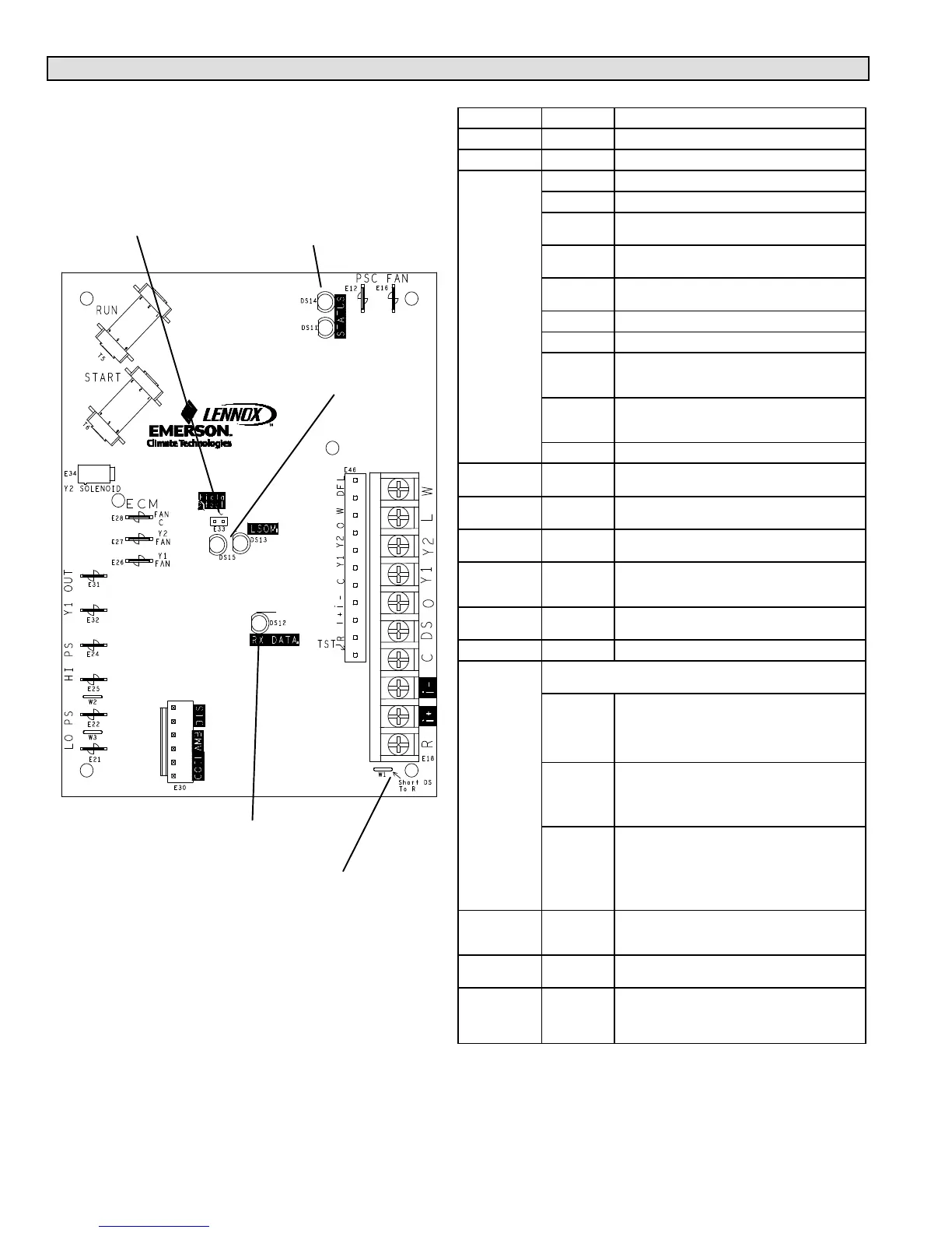
Air Conditioner Control (A175) Jumpers and Terminals
Table 3. Main Control Jumpers and Terminals
Board ID Label Description
E12 PSC Fan 240 VAC output connection for outdoor fan.
E16 PSC Fan 240 VAC input connection for outdoor fan.
E18
W 24VAC output for defrost auxiliary heat output.
L Thermostat service light connection.
Y2
24VAC thermostat input/output for second stage
operation of the unit.
Y1
24VAC thermostat input for first stage operation of
the unit.
O
24VAC thermostat input for reversing valve
operation
DS Humiditrol Input
C 24VAC system common
i−
Input/Output − RSBus data low. Used in
communicating mode only with compatible indoor
thermostat.
i+
Input/Output − RSBus data high. Used in
communicating mode only with compatible indoor
thermostat.
R 24VAC system power input
E21 and E22 LO−PS
S4 connection for low−pressure switch (2.4
milliamps @ 18VAC)
E31 and E32 Y1 OUT
24VAC common output, switched for enabling
compressor contactor.
E24 and E25 HS−PS
S87 connection for high−pressure switch (E25) and
24VAC (E24) to A177 R" input.
E26 Y1 FAN
First Stage and second stage basic and precision
dehumidification ECM fan motor 24VDC output
connection 1.
E27 Y2 FAN
Second stage basic and precision dehumidification
ECM fan motor 24VDC output connection 2.
E28 FAN C ECM common connection for ECM fan.
E30
Six position square pin header E30 provides connections for the
temperature sensors.
DIS
(YELLOW)
PINS 5 and
6
DIS 5 Discharge line temperature sensor supply.
DIS 6
Discharge line temperature sensor return.
Range is 35ºF to 310ºF. Sensor is clipped on a 1/2"
copper tube.
AMB
(BLACK)
Pins 3 and
4
AMB 3 Outdoor ambient temperature sensor
supply.
AMB 4 Outdoor ambient temperature return.
Range is 40ºF to +140ºF
COIL
(BROWN)
Pins 1 and
2
COIL 1 Outdoor coil temperature sensor supply.
COIL 2
Outdoor coil temperature sensor return
This model does not utilize a coil sensor. The cable
harness assembly for the sensors incorporates a
10K resistor between pins 5 and 6.
E33 Field Test
This jumper allows service personnel to defeat the
timed off control, initiate or terminate a defrost and
field programming of unit capacity feature.
E34
Y2
Solenoid
Second−stage compressor output.
W1
Short DS To
R
Cut for Humiditrol (EDA) application. This sets the
outdoor fan speed to predefined speed. See table
15 for set speed based on unit capacity size. Use
only in two−stage units.
COMMUNICATING
STATUS INDICATOR
TWO−STAGE
DS12
DS13 and DS15
LED ALERT
CODES
DS11 and DS14
Table 3 provides additional information concerning
jumpers, links, and connections for the A175 Main
Control.
LED ALERT
CODES
FIELD TEST
PINS (E33)
FOR HUMIDITROL
(EDA) APPLICATION
(TWO−STAGE UNITS
ONLY)
W1

 Loading...